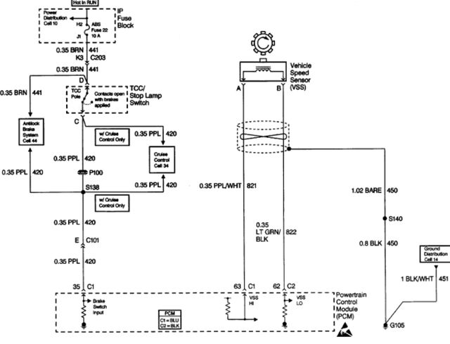
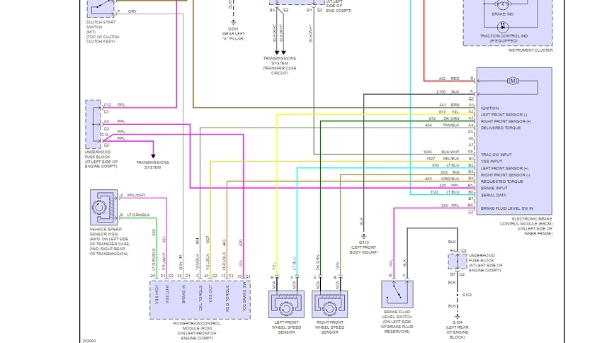
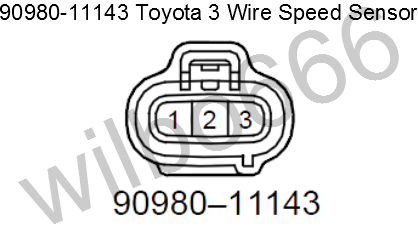
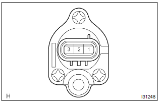
The photos below are looking down at the sensor from above there are ford and gm versions of the vss. The wiring harness for the 2wd is extended to the rear vss on the transfer case the vehicle speed sensor adapter just hooks the 2 wiring harnesses together.

Civic Vss Wiring Diagram The Speedometer In My 1994 Honda
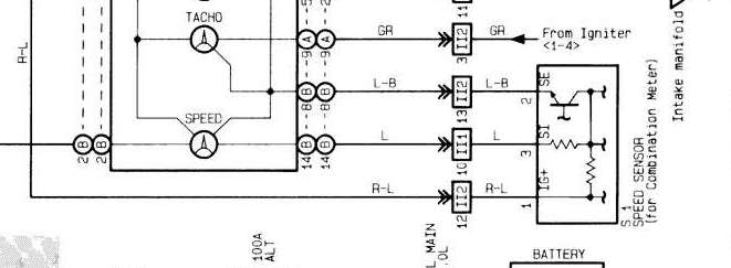
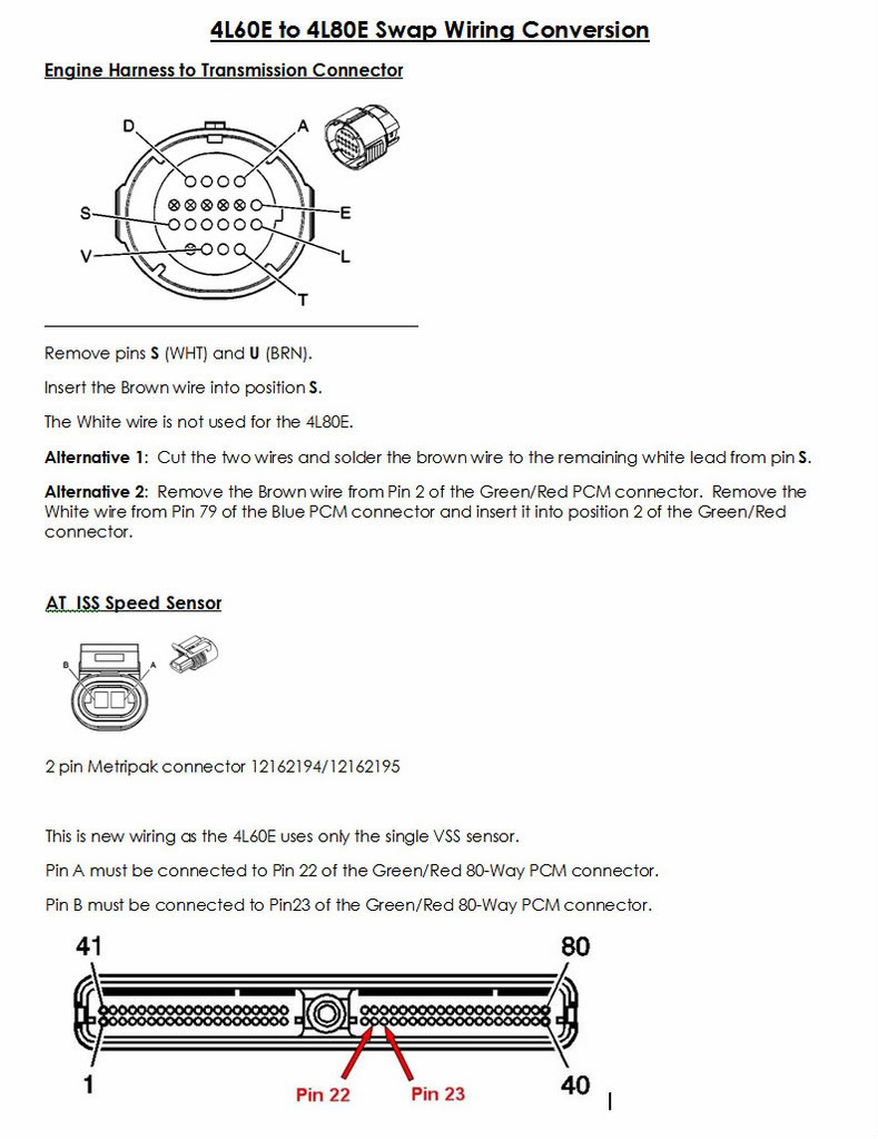
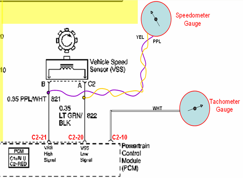
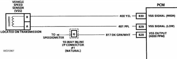
Vss wiring diagram. The yellow is vss high according to the camero diagram. A very basic vss system. Find out how to access autozones vehicle speed sensor vss repair guide for silverado 2008. On the left is the 4 pulse vss used on manual transmission camaros with tpi or camaro v6 and lt1 engine with a. You should be able to find the same wire at the ecm from a diagram or the harness builder. Because of the importance of the vehicle speed sensor we cannot recommend.
The vss is located on the passenger side of the transmission at the rear inline with the output shaft. Joined jun 3 2009 19 posts. 01092018 01092018 6 comments on 1992 camaro 5 speed vss wiring diagram. This system consists of a vss sensor system wiring and the powertrain control module pcm. On these early units the vss signal goes directly to the pcm. A small gauge wire is ok almost no current on it.
We supply a two wire connector for these. The vss sen sor is located on the side of the trans mission or transfer case. P email protected registered. It may not be necessary but if you tie into the plug at the transmission i would use either a shielded wire or a twisted pair with one grounded. The ac converter is built into the pcm itself. Disengage the wiring harness connector from the vss.
Volkswagen jetta golf and cars 2000 05 main wiring diagram cabrio 1999 repair guide. Vehicle speed sensor replacement. Hi that vehicle speed sensor adapter is just a solid plastic part that has 2 solid wires going through it. My 85 c4 project is just about ready to rolli have all my upgrades done 383 stroker zf 6 speed and 373 gears. Jump to latest follow 1 5 of 5 posts. Find out how to access autozones main wiring diagram equivalent to standard.
They are oriented upward toward the floorboard. Driveright 600e console harness cable adapter cable white red male disconnect butt splices 3 red wire with fuseholder in line splice in line splice butt splices 2 blue wires with in line fuses green yellow red red black black t tap connector unswitched 12v ground ground spade. Wiring diagram the diagram below is an example of the driveright 600e vss wiring. This early system had very few. Vss and speedometer wiring diagram. Discussion starter 1 jan 8 2010.
Using a digital volt ohmmeter dvom measure the resistance ohmmeter function between the sensor terminals. Your vehicle could start to act like it has a bad coil pack or throttle position sensor and after testing those you may still come up empty handed. If the resistance is 190250 ohms the sensor is okay. Autozones repair guides tell you what you need to know to do the job right. Vehicle speed sensor testing. Rather than change vss drive and driven.
Turn the ignition switch to the off position. Testing either a 2 or 3 wire hall effect speed sensor is a relatively easy task and one that can save you quite a bit of money in the long run. Also the adapter harness appears to go somewhere into a big harness reality is it just goes into the large harness and back.
