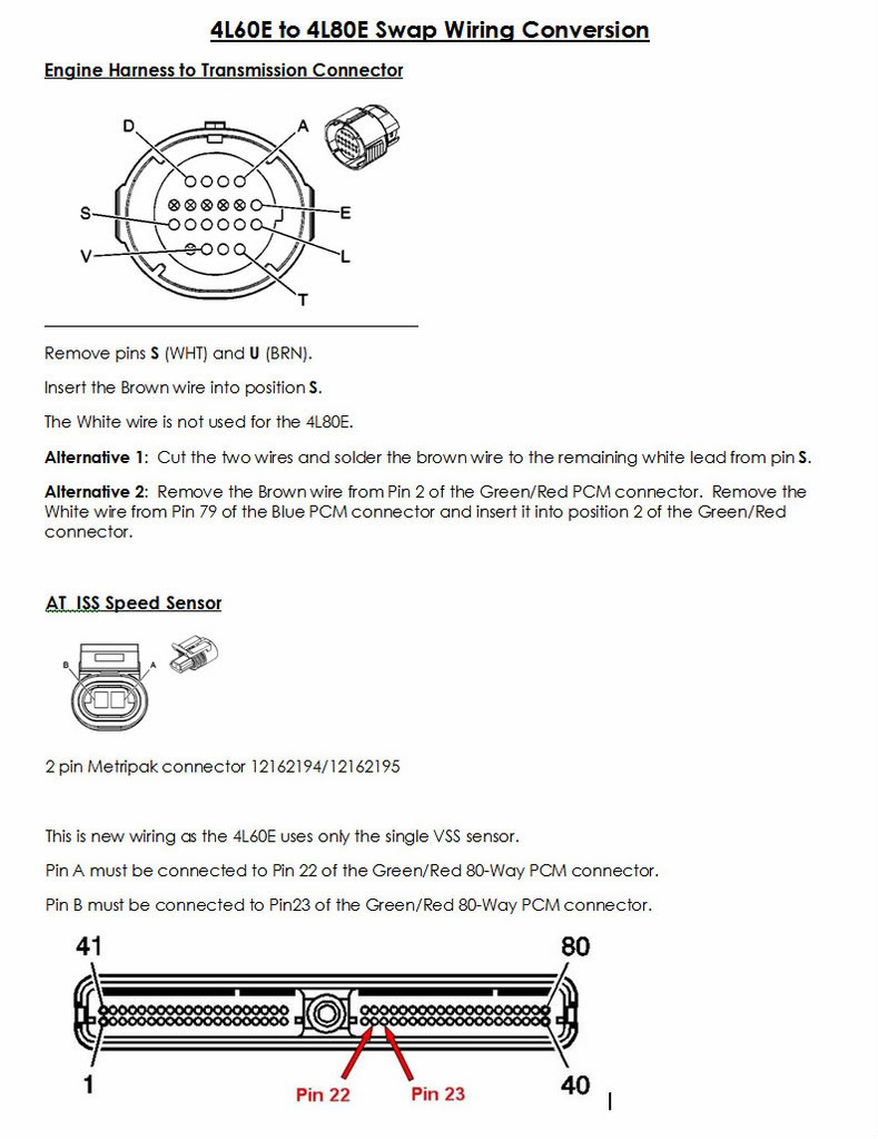
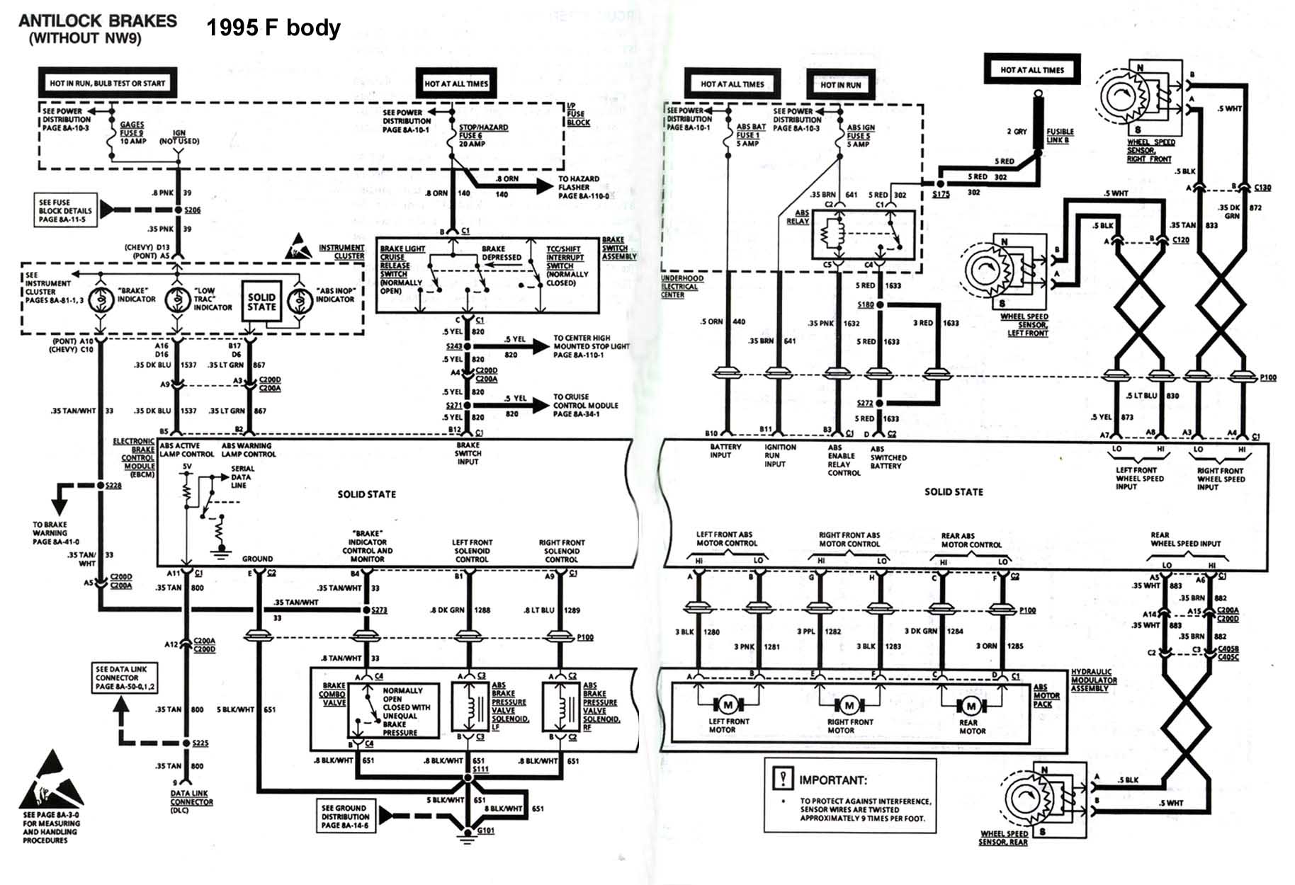
Each component ought to be set and connected with other parts in particular way. This harness will not work with a 4l60e4l80e electronic transmission.

Need Help Finding Correct 1995 Tbi 454 4l80e Harness Pinout
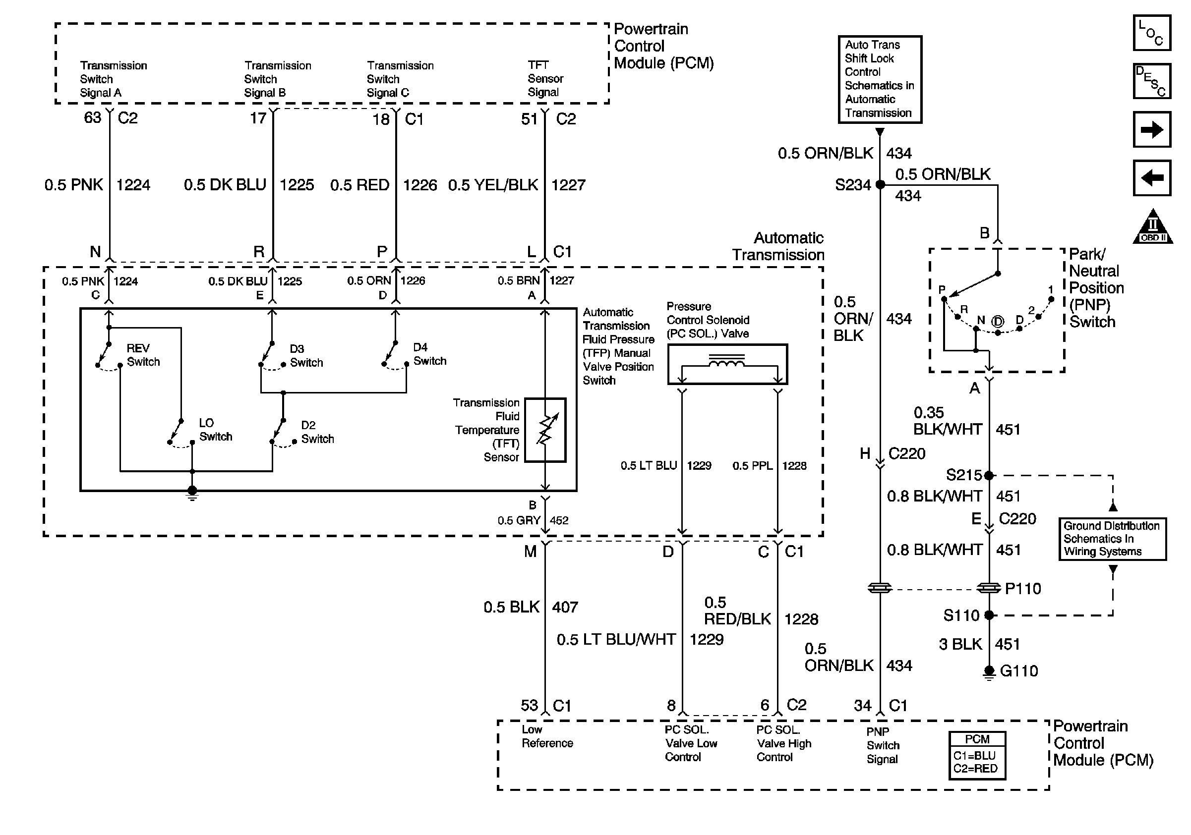
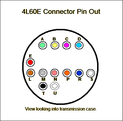
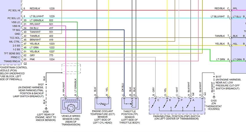
4l60e vss wiring diagram. Includes vss vehicle speed sensor wiring transmission wiring if applicable and. There is an early and a late model of the 4l60e transmission. 4l60e transmission wiring diagram 1995 4l60e transmission wiring diagram 4l60 transmission wiring diagram 4l60e 44 transmission wiring diagram every electric structure is made up of various different pieces. Speed sensor iss signal transmission tft sensor signal low reference grotmd not used torque converter clutch ucc solenoid vúe control torque converter clutch pulse width modulation tcc solenoid valve control input speed sensor iss low signal p n position switch signal k v wire 05 l gn 05 ye l bu 05 rd 035 035 ye 035 035 ogbk. Otherwise the structure wont function as it should be. The difference is the addition of the lockup feel solenoids aka.
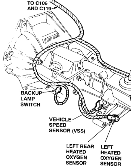
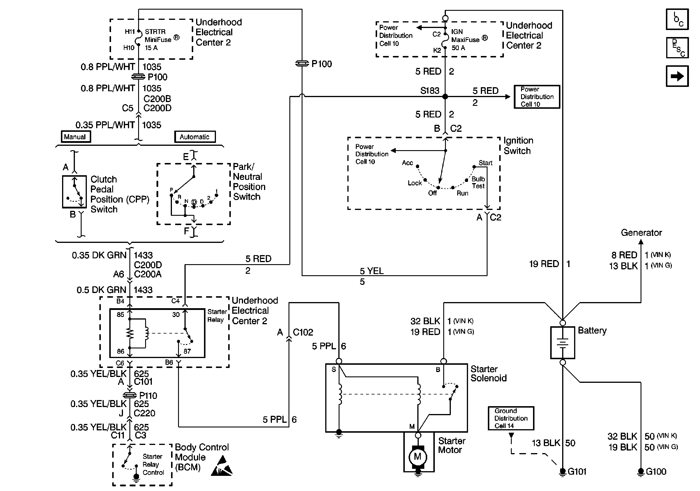
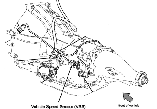
Not merely will it assist you to attain your desired final results more quickly but additionally make the entire method easier for everyone. 4l60e wiring diagram you will need a comprehensive expert and easy to understand wiring diagram. With such an illustrative guide you will be capable of troubleshoot stop and total your projects without difficulty. 4l60e wiring diagram 1993 4l60e wiring diagram 1994 4l60e wiring diagram 1995 4l60e wiring diagram every electric arrangement consists of various different pieces. If not the arrangement will not function as it ought to be. Vss vehicle speed sensor on 2wd vehicles is in transmission extension housing on 4wd vehicles the vss is in transfer case.
Each part ought to be placed and connected with different parts in specific manner. Input speed sensor trans 4l60e to 4l80e this harness is designed to be a complete wiring system for the fuel injection system used on general.
