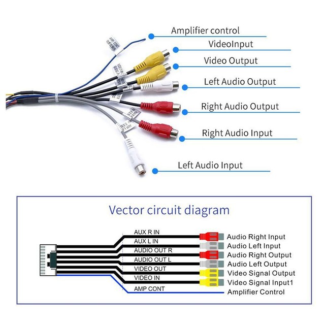
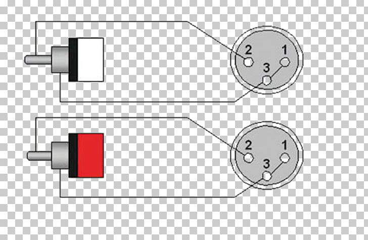
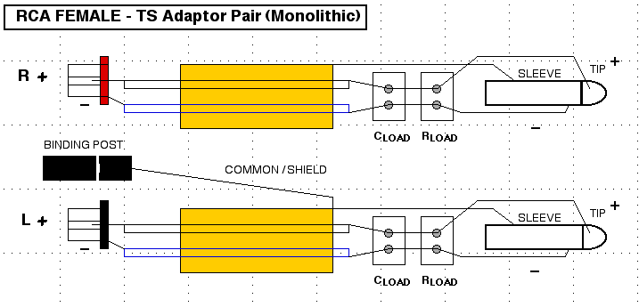
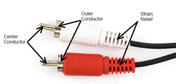
A wiring diagram is a streamlined standard pictorial representation of an electric circuit. An additional third connector on an rca cable will be yellow for composite video.

Vga To Rca Wiring Diagram Vga To Yellow Rca Diy Wiring
Rca wiring diagram. If not the structure wont work as it ought to be. A wiring diagram typically gives info about the loved one position as well as setup of tools as well as terminals on the gadgets to assist in building or servicing the tool. According to rca to usb wiring diagram you will find just four wires used from the cable. Rca audio cables have two connectors. Each part should be set and linked to different parts in specific way. Usb to rca cable wiring diagram usb to rca cable wiring diagram every electric structure consists of various diverse components.
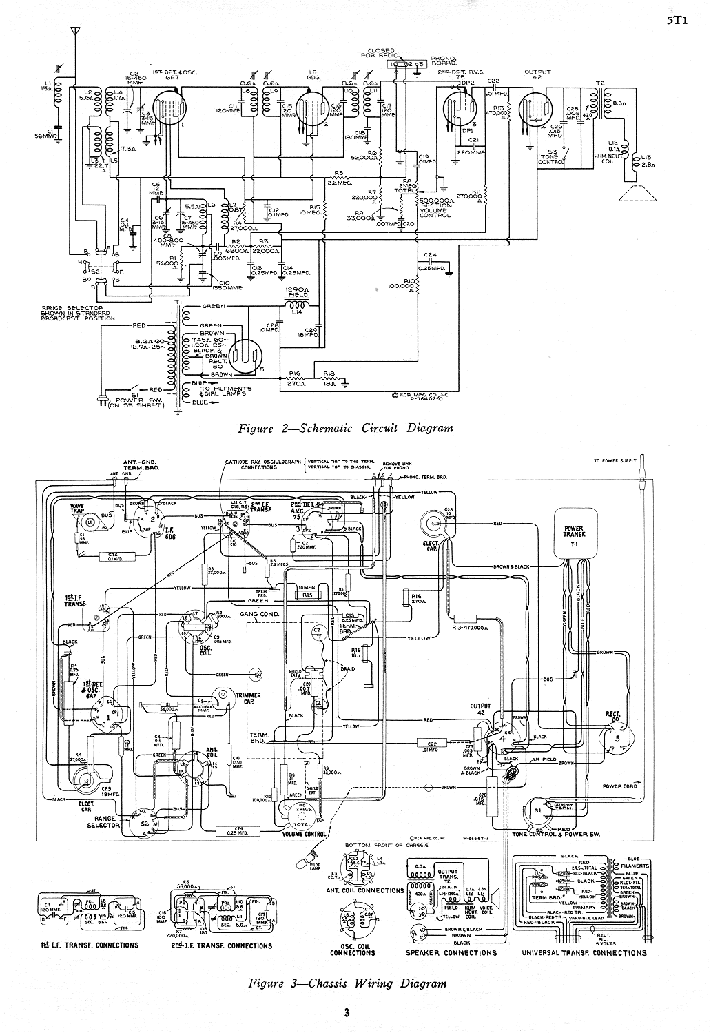
Each part should be set and connected with different parts in specific manner. 1 rca c10 radiotron manual audio rca ba 1a two stage preamp schematic mi9377 new mi12246 new rca 2cw4 6cw4 13cw4 nuvistor rca 2t51 sams 111 11 rca 5t1 amsw radio service manual rca 6cw4 nuvistor an 191 rca 6ds4 2ds4 nuvistor rca 6l6pp rca 6l6pp schematic rca 6t2 6k2 rca 6t71 sams 113 7 rca 6v6pp rca. Otherwise the arrangement will not work as it should be. Rca wiring diagram rca cable wiring diagram rca connector wiring diagram rca converter wiring diagram every electrical arrangement is composed of various different parts. Typically it uses black green white and red wire colors. The red one is for sure wire with dc power of 5 liter.
Connections are made by pushing the cables plug into the female jack on the device. It shows the parts of the circuit as simplified shapes as well as the power as well as signal links between the tools. Red right stereo and white or black for left stereo. Rca diagrams schematics and service manuals download for free. Typical rca cables will have two or three color coded connectors. Black wire serves as floor exactly like in any other device.

