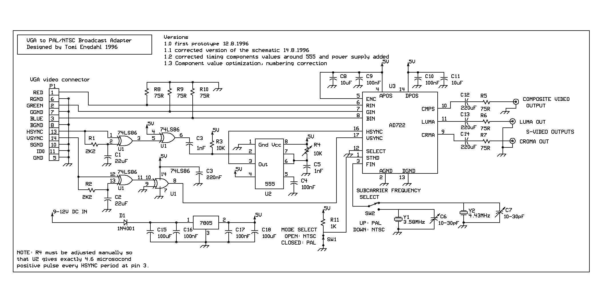
An exor gate from ic1 74hc86 combines the separate v sync and h sync signals into a composite sync signal. For power some cameras have terminals to accept bare wire.
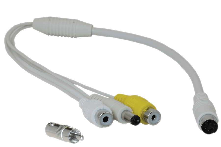
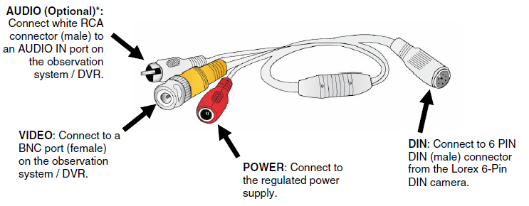
Rca Or Bnc And Power To 6 Pin Din Converter Cable
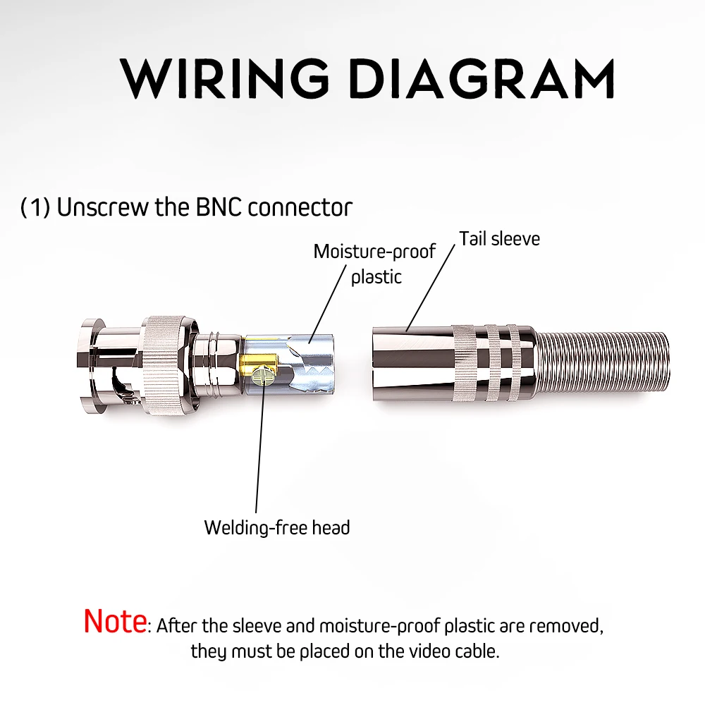
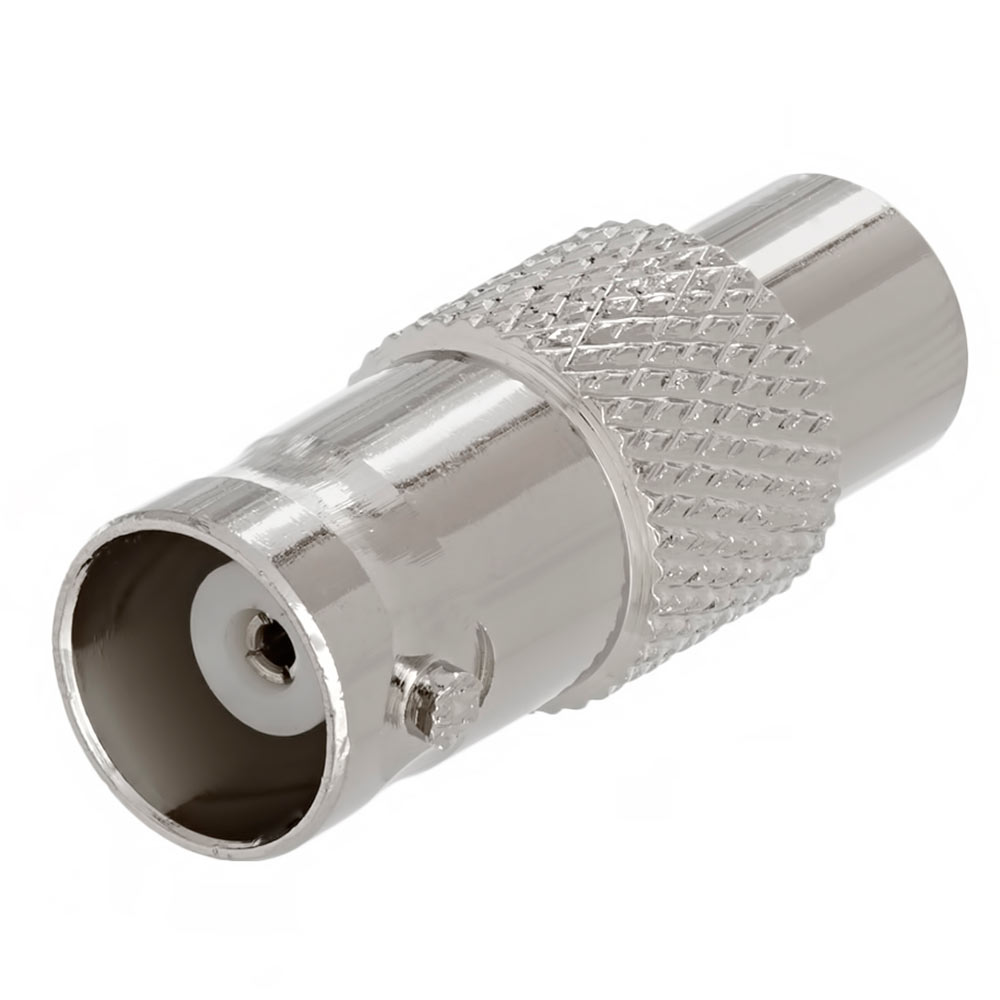
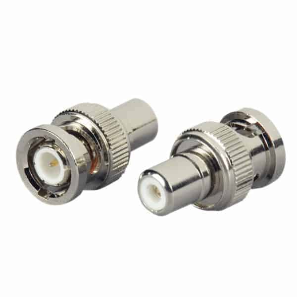
Bnc to rca wiring diagram. Here is the schematic diagram of bnc connector parts and components. Bnc to usb wiring diagram bnc to usb wiring diagram there are a number of types of electronic gadgets on the market. Others require a connector be attached to the wires to plug into the camera. Connect cctv camera to tv with rca cable without dvr youtube how to splice bnc to usb wiring diagram. To connect the cctv camera to a tv you need to adapt the bnc connector to rca which is the input available on the tv. Mengakali agar cctv bisa langsung dilihat di tv biasa menggunakan kabel rca tanpa harus disambungkan dulu ke dvr lumayan simple dah hanya dibutuhkan kabel penyambung saja yaitu bnc to rca.
Hd how to splice bnc to usb wiring diagram. Just connect it to the cable and to the power. How to splice bnc to usb wiring diagram images. Initially designed as a miniature version of the type c connector bnc is a type of connector used with coaxial cables such as rg58 and rg59 rf applications that require a quick connector suitable for uhf and constant impedance over a wide spectrum. An additional third connector on an rca cable will be yellow for composite video. Bnc connectors are crimped onto the rg59 coaxial cable to be plugged into the cameras video port.
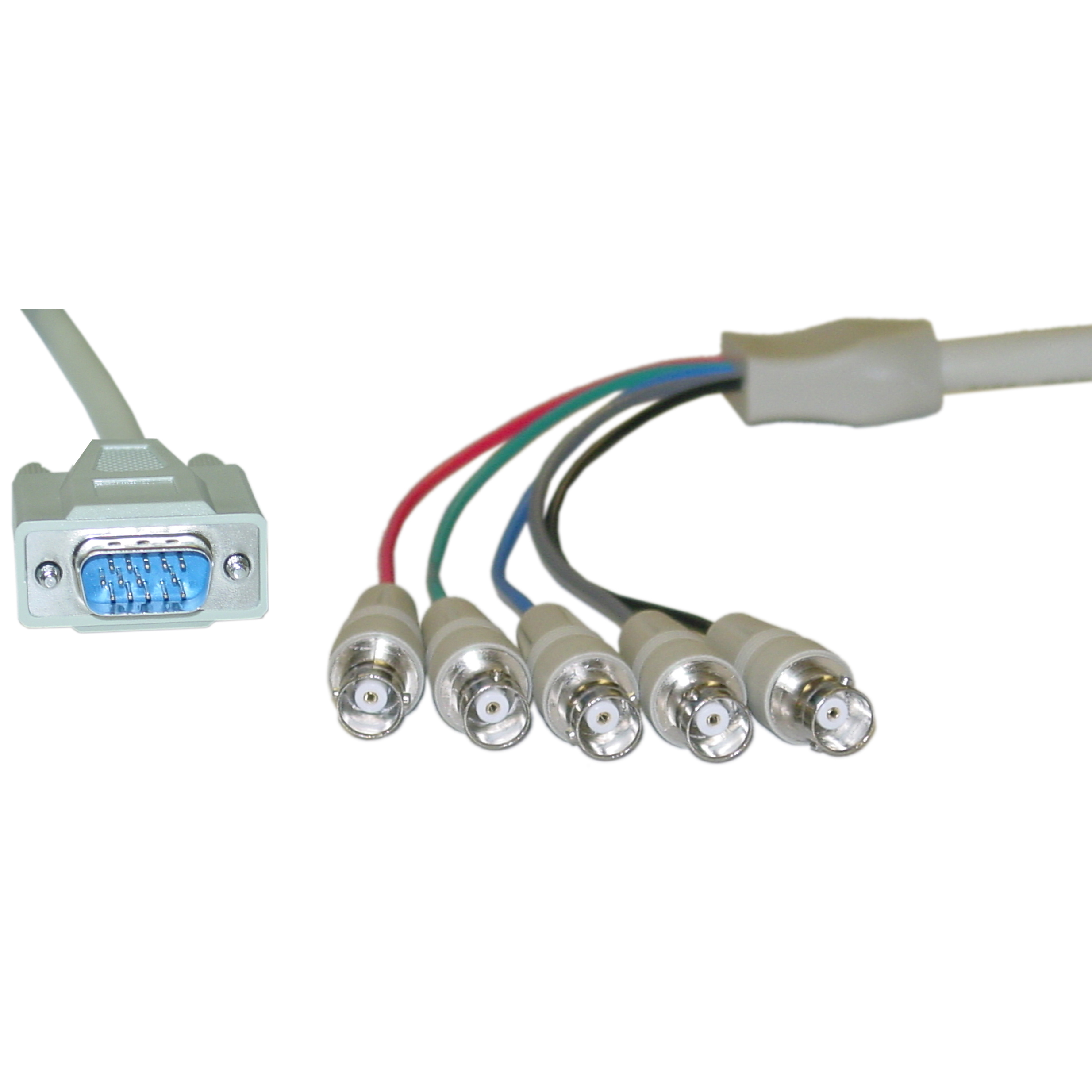
Connections are made by pushing the cables plug into the female jack on the device. Red right stereo and white or black for left stereo. Vga bnc adapter circuit diagram. See an example of this type of adapter in the image below. Rg59 siamese coax cable wiring guide for analog cctv cameras ampamp. Bnc to rca adapter.
The following wiring diagram shows that how to connect an analog ptz camera to the dvr and joystick ptz controller. 30w1 00200 picture the red wire is positive and the black wire is negative. The bnc cables are used for video signal transmission while the rs 485 cables are used to control the camera movement and rotation by connecting it to the joystick ptz controller or dvr system. Video balun wiring diagram along with video balun connector diagram as well as cat5 video balun wiring diagram additionally tv. Since the sync in dos modes is often inverted compared to the modes commonly used by windows the output of ic1a is inverted by ic1b. Jp1 can then by used to select the correct operating mode.
The signal carrying pin protrudes from the plug and often comes into contact with the. It can also link device to a power source for charging function. Video balun wiring diagram all kind of wiring diagrams 4 channel bnc to rj45 cat 5 video transceiver passive cctv utp video balun vbp video balun connector diagram pro built camera wiring diagram. Power jack plug adapter connectors are used for power connection. The cable can be utilized to transfer data from one device to another. The majority of them use usb cable.
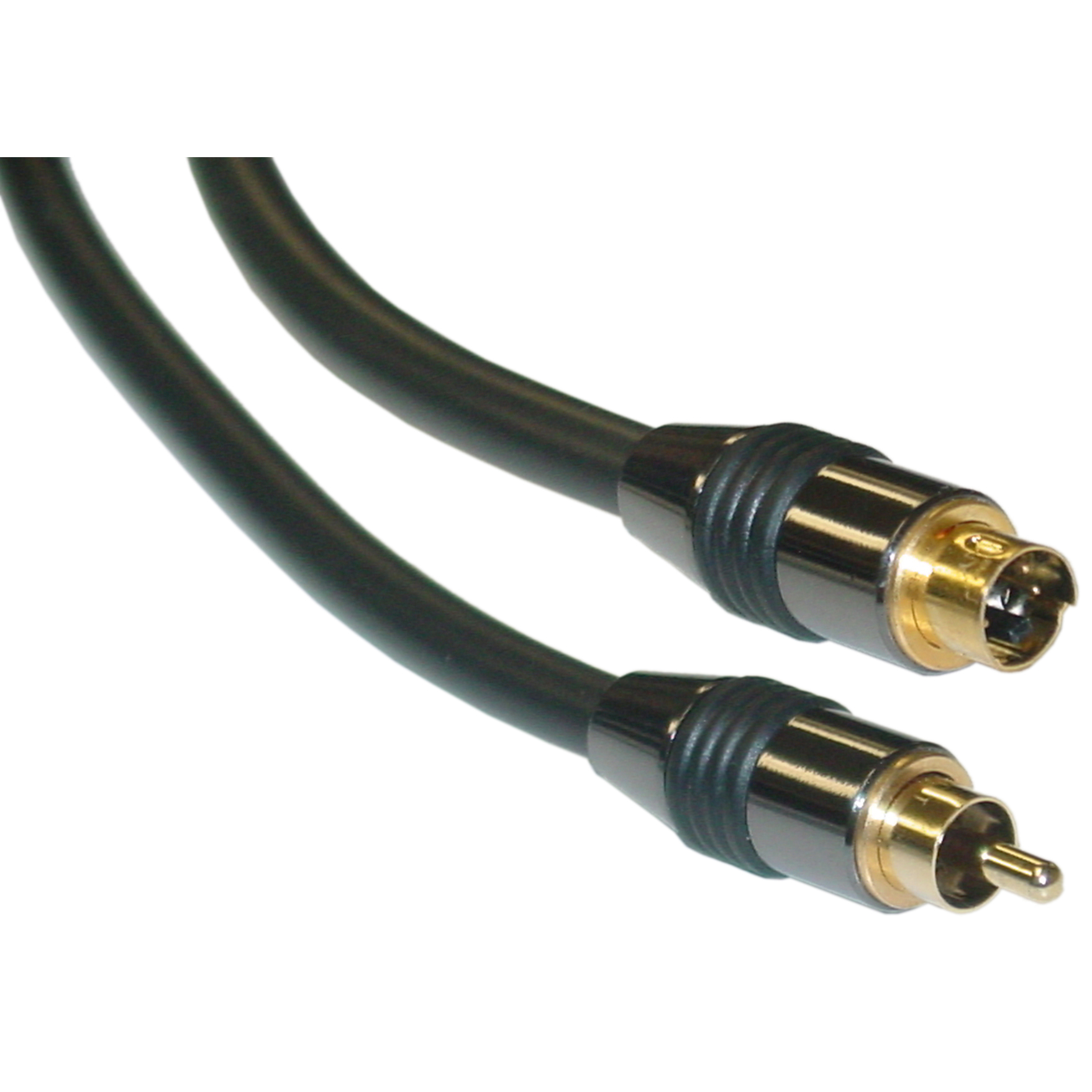
Rca audio cables have two connectors. Power jack plug adapter connector.


