The mppt solar charge controllers are suitable for 12v 24v 48v off grid solar panel module and also applied for the grid tie module of which the open voltage does not exceed the specified maximum input voltage. Volt meter the led voltmeter provides information regarding your battery voltage.

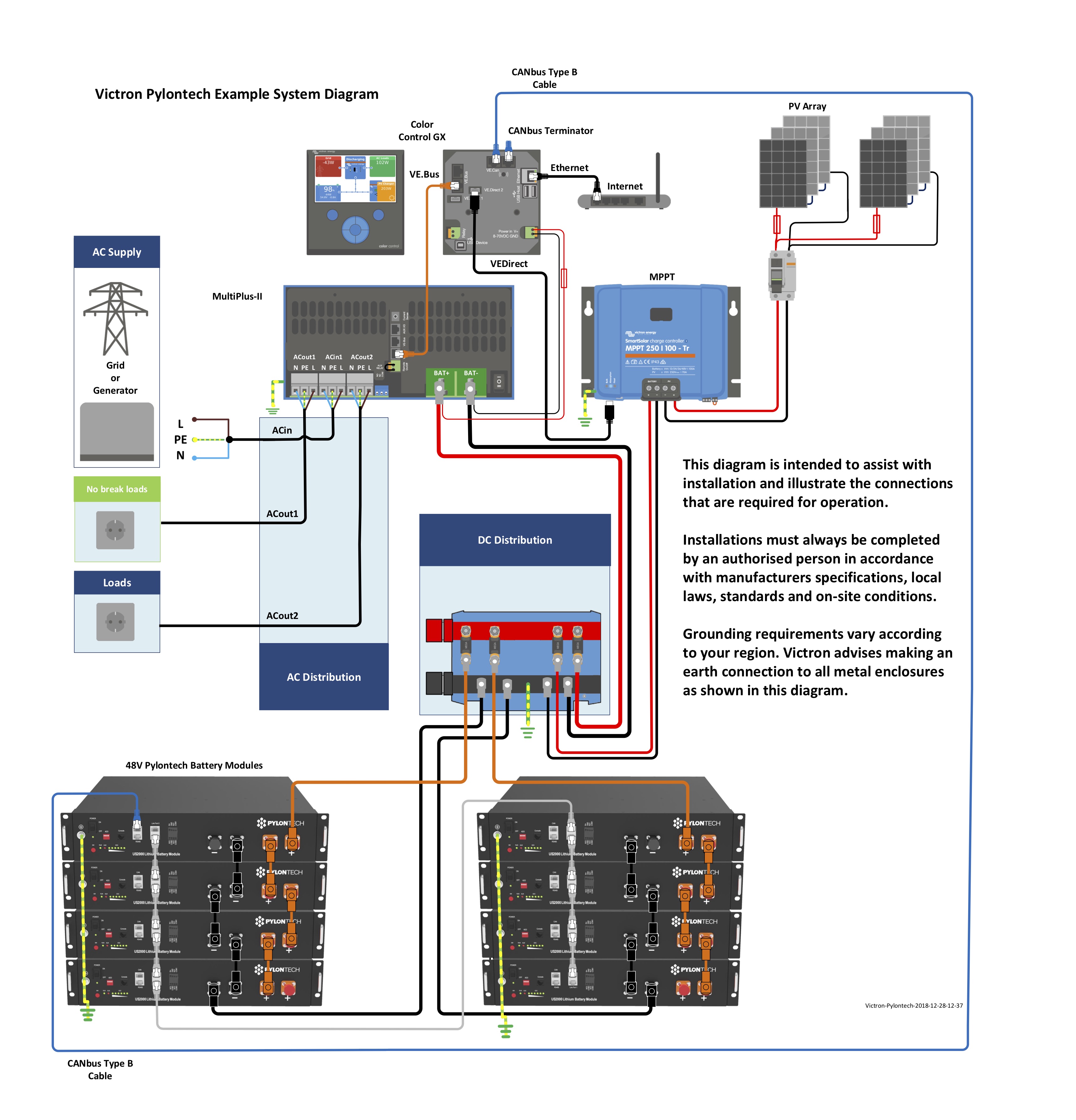
Demo Electrical System Layout With Victron 24 Volt Multiplus
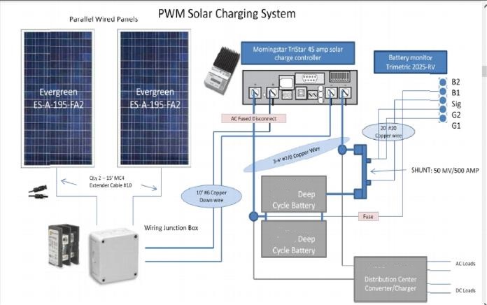
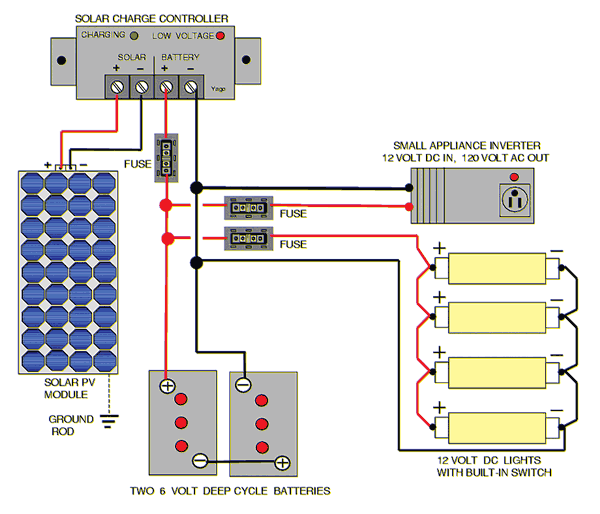
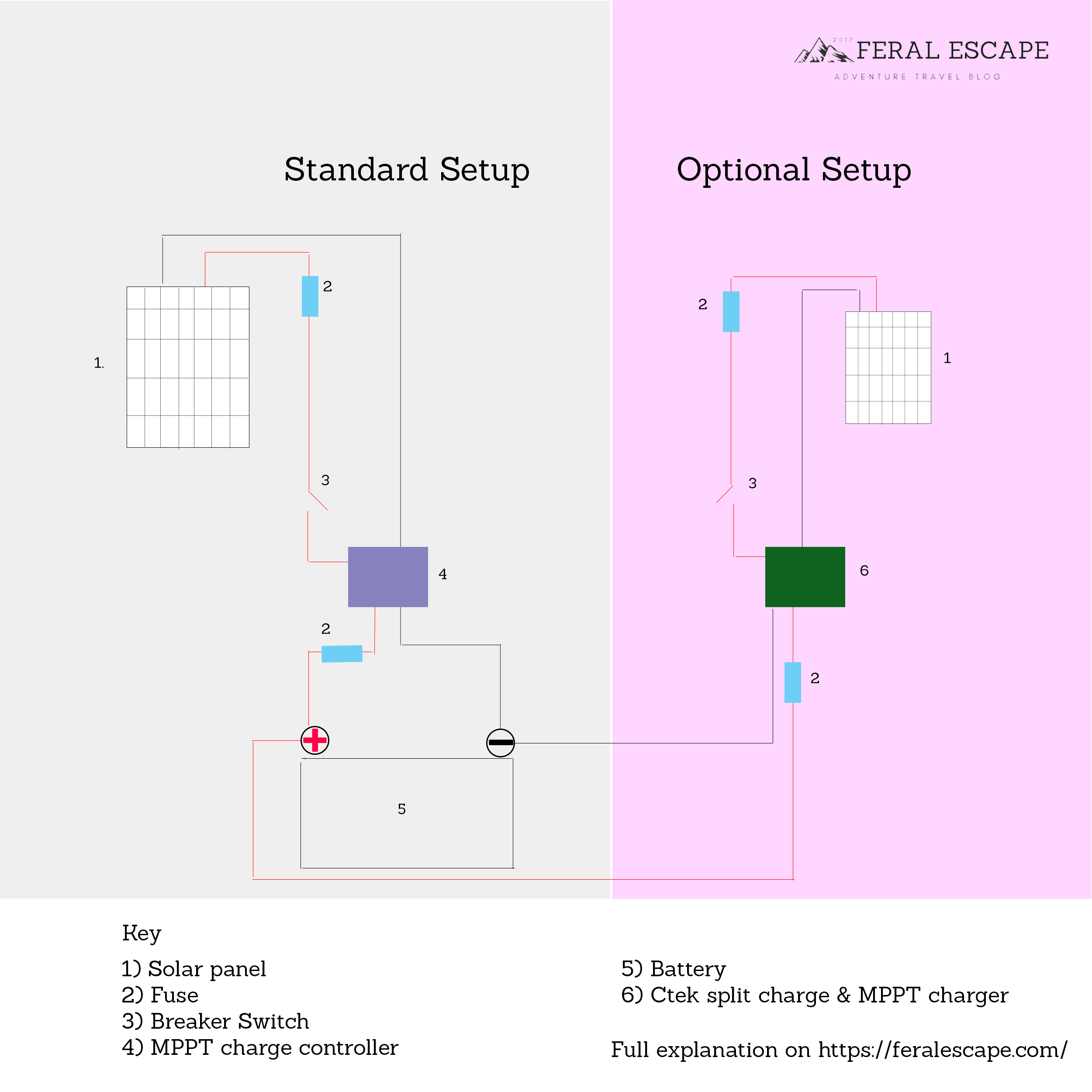
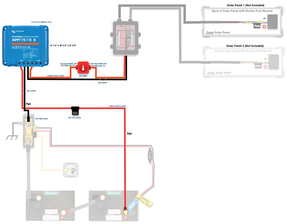
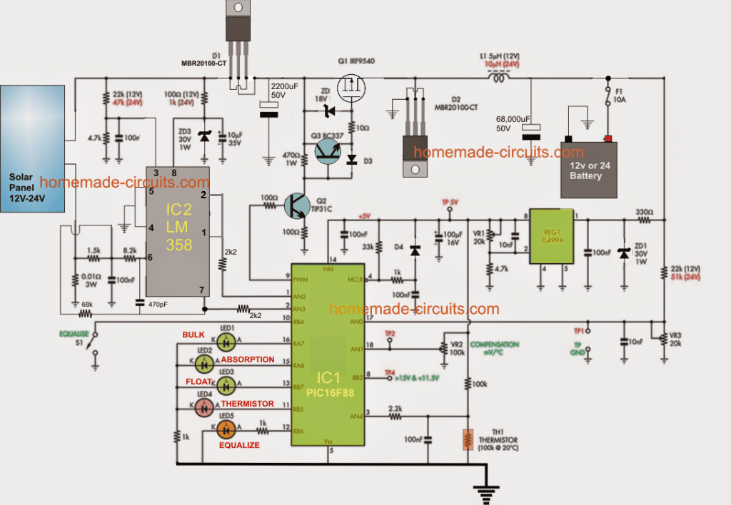
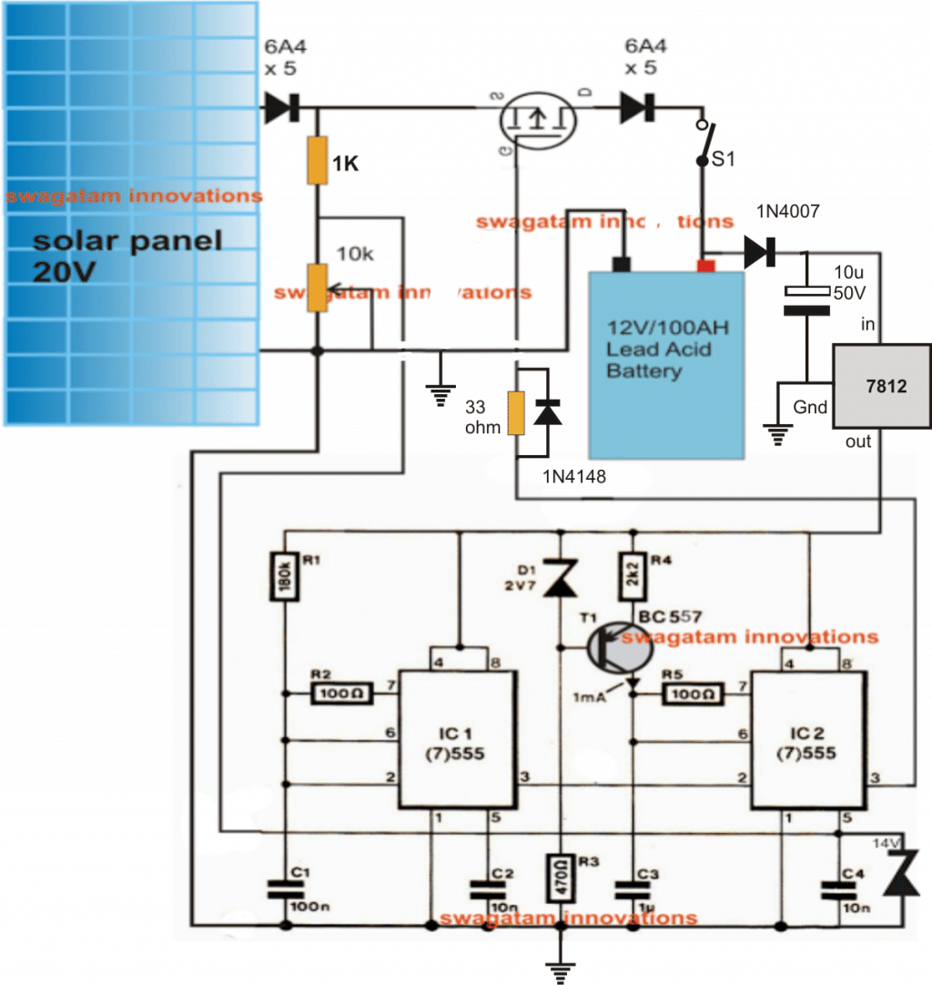
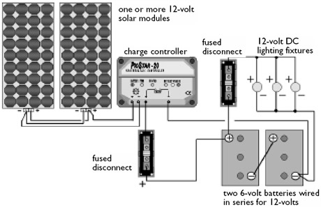
Mppt wiring diagram. This diagram gives information of circuits components. Wiring unlimited rev 06 4 1. On the other hand this diagram is a simplified variant of the arrangement. This is useful in the operation of your system. The schematic diagram above illustrates how the prostar mppt regulates power to batteries and a direct current dc load in an off grid system. The wiring diagram of the solar charge controller and dc load is shown as below.
Mppt can be used in conjunction with a mechanical tracking system but the two systems are completely different. Sunlight contacts the solar modules which convert solar into dc electrical power that it delivers to a charge controller. Introduction welcome to wiring unlimited a book about electrical wiring of systems containing batteries inverters charger and inverterchargers. 300 watt 12 volt monocrystalline solar starter kit w mppt charge renogy wiring diagram. Victron mppt solar regulator the bluesolar mppt charge controller is able to charge a lower nominal voltage battery from a higher nominal voltage pv array and is rated at max 100v open circuit voltage on input. We will explain the importance of getting.
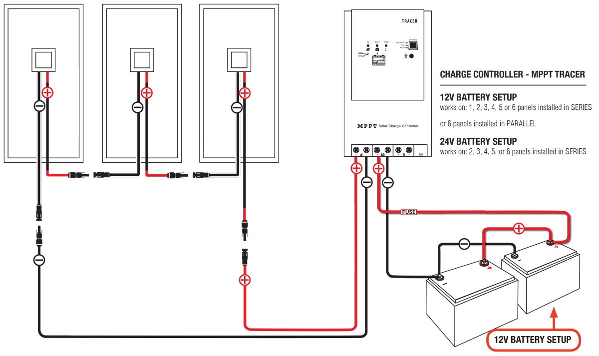
Connect pv panel module to mppt charge controller. Quattro 5kw 120vac 12vdc 600ah li vebus bms generator mppt bmv ccgx orion tr smarts quattro split phase 120 240vac 24vdc setup 600ah li ve bus bms generator mppt bmv ccgx quattro system example 5kw 24v 120v ac. Connecting the solar panel charge controller mppt or pwm are the same solar battery and the pv array in the right way is the essential work before enjoying the solar energy. Cypress mppt solar charge controller is a battery charger and load controller with integrated led driver which features a smart tracking algorithm that maximizes energy harvest from solar panels. The diagram offers visual representation of a electric structure. Solar panel charge controller wiring diagram and step by step guide for off grid solar power system wiring.
This makes the procedure for building circuit simpler. With this book we aim to explain wiring basics of electrical systems. Solar panel charge controller wiring intro. Hello sirplease may explain a difficulty and ask a question based on itbased on the first and second diagramsthat is the buckboost configurationi checked online for awg wire current and frequency rating and found that the thickest wire to operate at 100khz with 100 skin depth is awg26but this wire is able to carry only 0361amp so to.








.jpg)
