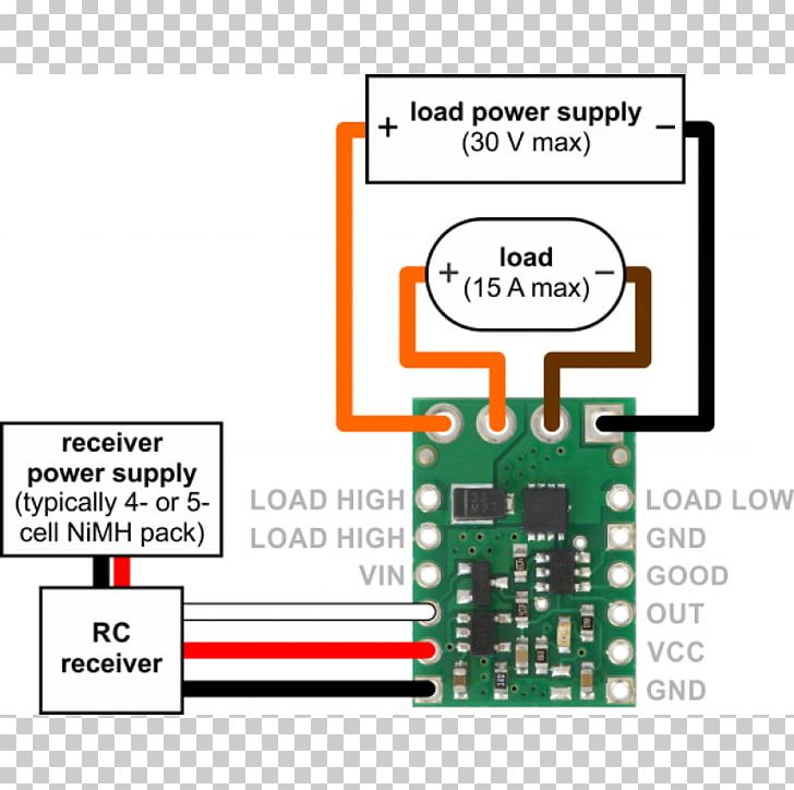
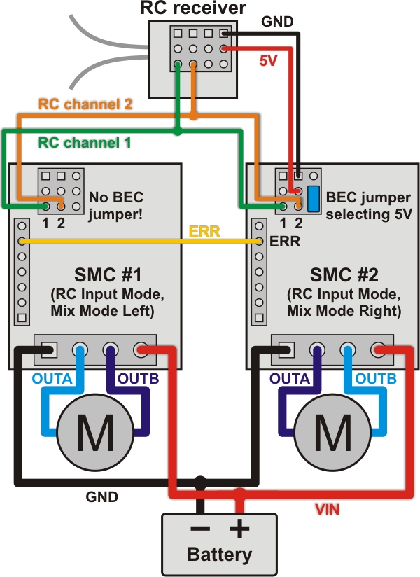
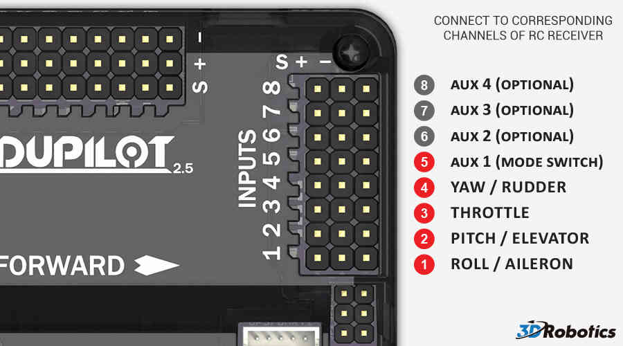
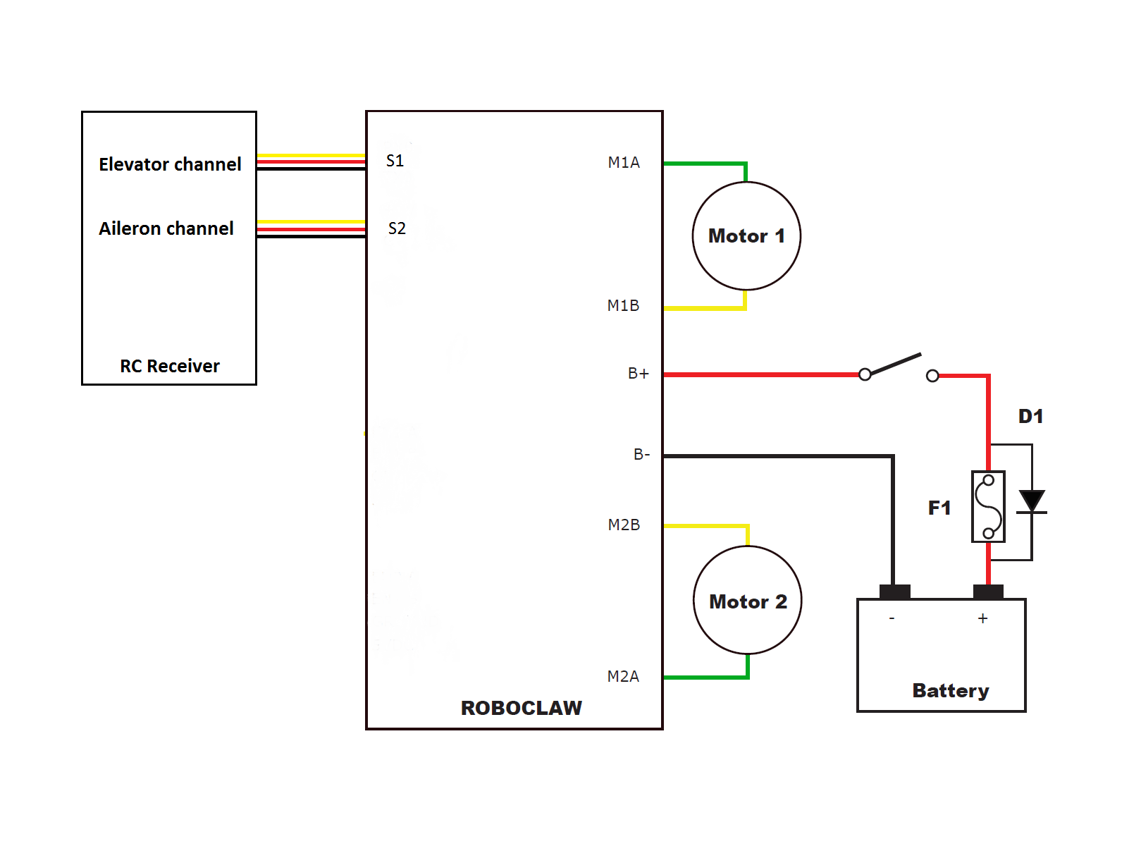
Wiring diagram for connecting an rc receiver to a simple motor controller. Using the rc channels the simple motor controller is constantly reading the two rc channels and making the measured pulse widths available via the usb and serial interfaces even when the controller is not in rc mode.

Castle Creations Bec Question
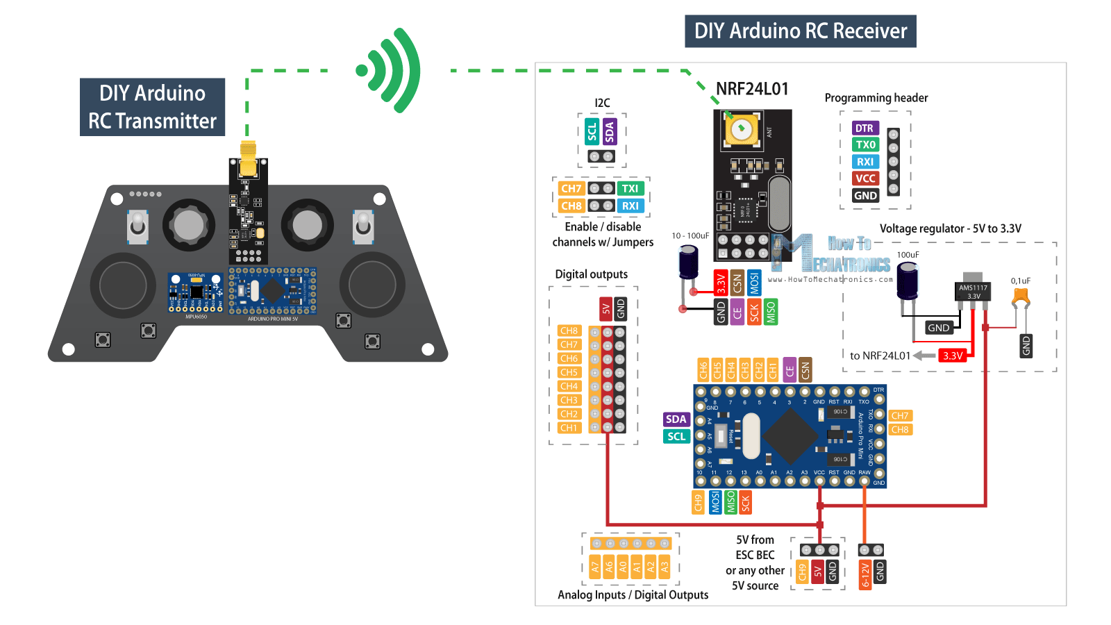
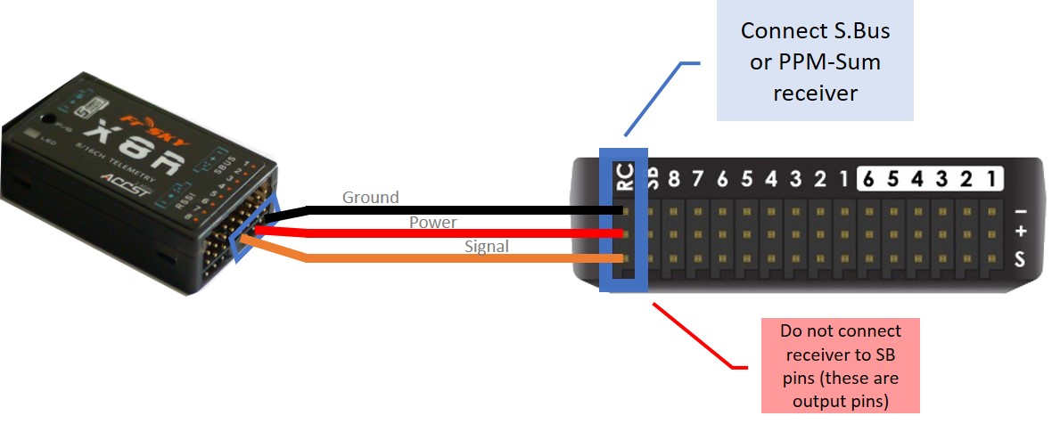
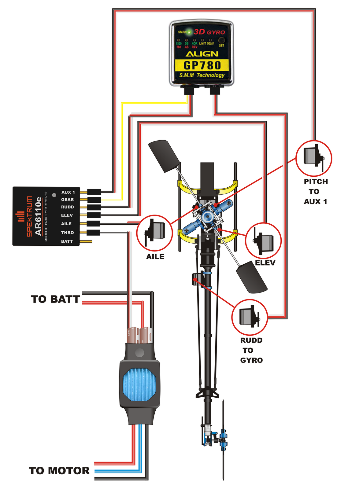
Rc receiver wiring diagram. The receiver above connects wirelessly to the the transmitter using a 24ghz frequency. The interface to the remote receivers is a 3 wire bus pins are as noted in the photo below pin color purpose 1 orange 3 3vdc 5 20ma max 2 black gnd 3 gray data spektrum remote receiver interfacing page 2 rev p3 the connector used in the spektrum remote is jst part number s3b zr lf sn digikey part 455 nd this mates to part jst zhr 3 digikey 455 nd see. It also sends a signal to the esc well talk about that later to tell it how fast the run the motor. 24ghz frequency is the standard frequency for rc planes. It shows the components of the circuit as simplified shapes and the capacity and signal friends surrounded by the devices. The receiver analyses the signal and adjusts it automatically in accordance with the current reception quality or field strength.
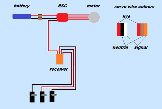
This means that the ipd receiver calculates the nominal servo position from the. The receiver runs off of 5v and sends signals the the servos to turn them. Powerful signals are passed on to the servos directly but weaker signals are post processed. Rc receiver wiring diagram posted at may 20 2020 821 by admin in design precious readers when you are searching the brand new rc receiver wiring diagram wiring layout collection to read this day rc receiver wiring diagram can be your referred wiring representation. Remote receiver interfacing spektrum rc. Rc car receiver wiring diagram wiring diagram is a simplified up to standard pictorial representation of an electrical circuit.
