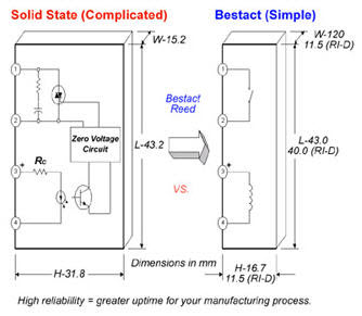
The d3pf series offer a number of enhanced features including led status lamp push to test button for manual relay operation a convenient finger grip for removing relays and a write on label that can be used for identifying the relay in multiple relay circuits. Octal relay wiring diagram e50muellerbau ibde.

Lessons In Electric Circuits Volume Iv Digital Chapter 5
Octal relay wiring diagram. Industrial plug in relay catalog supplement 4 wiring diagrams viewed from pin end 8 and 11 pin octal base relays premium line premium line 12a 8 pin octal socket dpdt premium line 12a 11 pin octal 3pdt 3tx7112 1nb13 12vac 1750 3tx7144 1e3 3tx7112 1nc13 24vac 1750 3tx7144 1e3. Also referred to as general purpose relays theyre widely available in both 8 and 11 pin models with 8 being the most common. Socket 8 pin octal relay great for experimenting. 8 pin octal relay wiring most relay sockets use 5 7 8 10 11 14 or 16 pins per blade there are many different socket receptacle styles examples include octal or circular sockets blade or lug sockets and square or this article explains how to adapt a standard octal relay driver to provide a random the recording of information from the input pin 2 247 8 10 through the multiplexers to the. Use anywhere you would use a normal octal tube socket but use screw terminal strips to attach wiring. Octal relay wiring diagram.
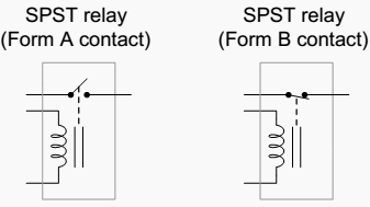
Wiring diagram arrives with numerous easy to follow wiring diagram instructions. This pinout image is only a 2 pole diagram for room on the page purposes but you can get the picture here with this one since a 3 pole will just have 1 more set of contacts. The d3pf are plug in type relays that feature an octal connection base. Relay 11 pin wiring diagram autocardesign. No need to mount socket and solder leads. Siemens energy automation inc.
Octal socket pins are numbered 1 through 8 clockwise when viewed from the bottom wiring side of the socket. 8 pin relay wire diagram wiring schematic wiring diagram 8 pin relay wiring diagram. An octal base relay like the one shown below is one of the most common electrical devices in use today. Control relay tutorial how a relay works. It is meant to help each of the common consumer in building a correct method. Theres a ridge that runs down the side of the stem on the relay base which mates with a cutout on the edge of the socket center hole.
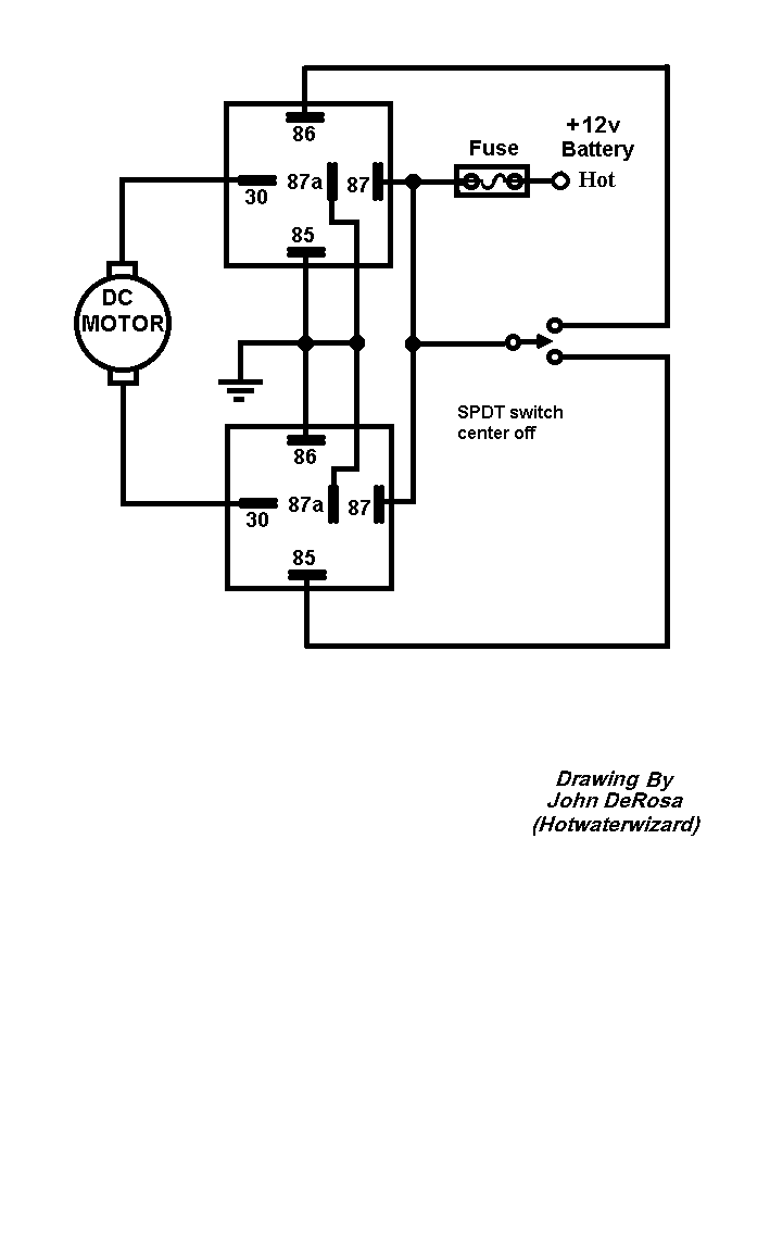
The square relay pinout shows how the relay socket is configured for wiring. These guidelines will likely be easy to comprehend and implement. Relay 11 pin wiring diagram wiring diagram is a simplified good enough pictorial representation of an electrical circuit shows the components of the circuit as simplified shapes and the capacity and signal links with the devices a wiring diagram usually gives instruction roughly the relative approach and union of devices and terminals on the devices.


