July 30 2018 by larry a. Wiring diagram 2 wire heating.

Xc 5035 Wiring Diagram Related Pictures Nordyne Electric
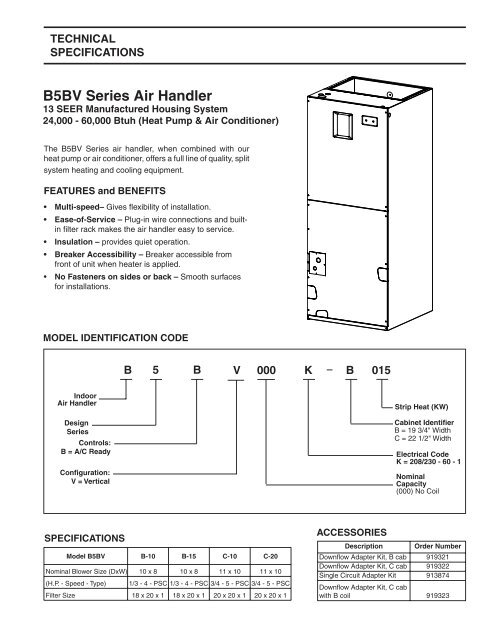
Nordyne air handler wiring diagram. Ne convient pas aux installations de plus de 150 volt a la terre. For nordyne models mg mm ms and mb 1. Nordyne furnace wiring diagram whats wiring diagram. Locate the cooling capacity of the air conditioning unit in the leftmost column of the appropriate section of table 1. Wiring diagram for b6vm series air handler. I just finished installing a new ac system and the air handler did not come with a wiring diagram for thermostat and compressor contact hookup.
Hand side of the air handler control box. Air handlers nordyne mb7bm series installation instructions manual. The air handler is a nordyne model b5bm 025 a the circuit terminals are. Wiring diagram for nordyne air handler. Couper le courant avant de faire letretien. Page 28 b6bm 240 vac 50 60 hz single phase 208 vac 50 60.
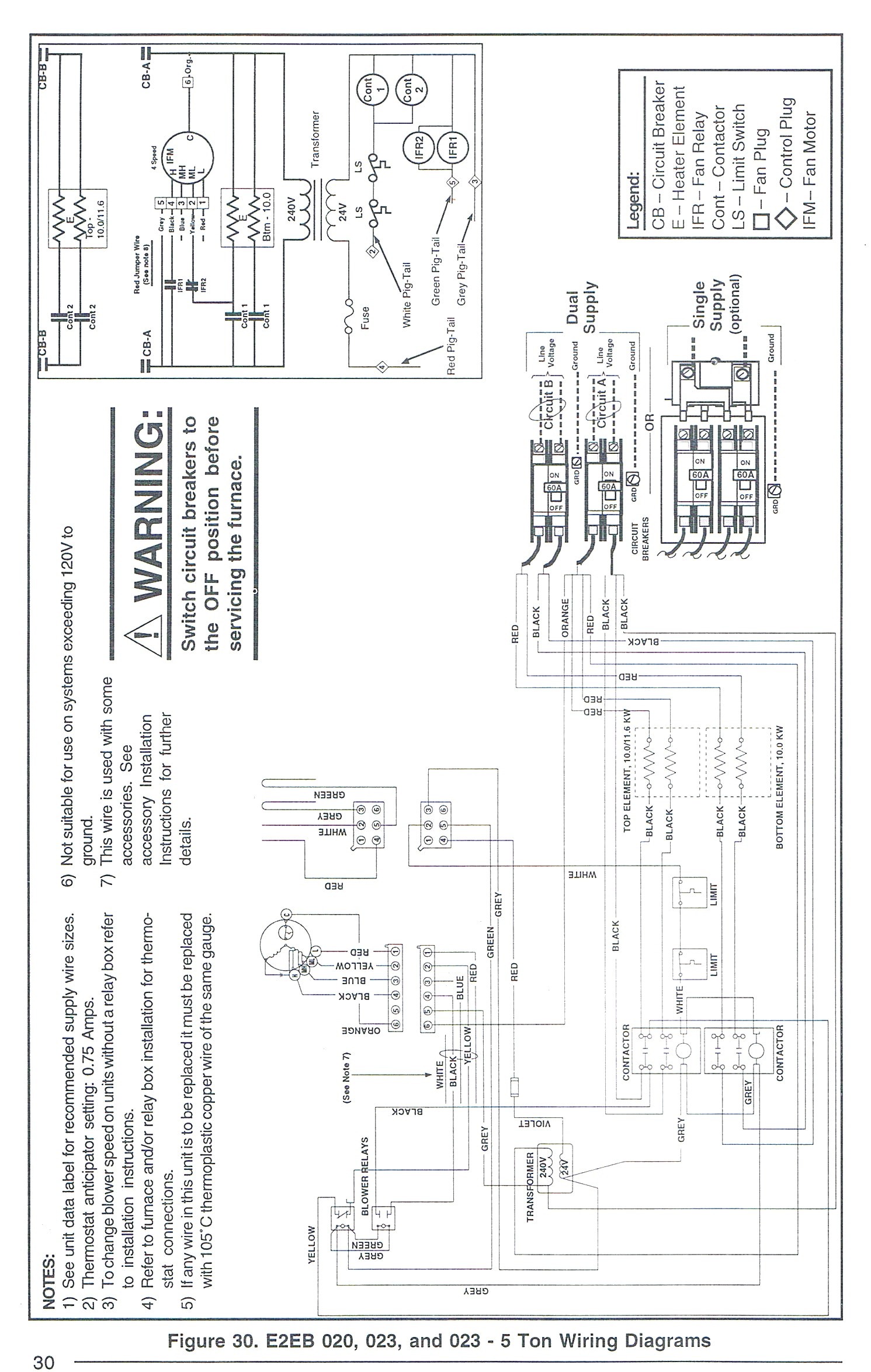
E3 series air conditioner heat pump air handler downflow upflow electric furnaces. Read across the. See furnaceair handler instructions for control circuit and optional relaytransformer kits. Dual capacitor h c f cch if equipped c. It shows the components of the circuit as simplified shapes and the power and signal connections in the middle of the devices. It reveals the parts of the circuit as streamlined shapes as well as the power and also signal connections in between the gadgets.
Nordyne e2eb 017hb furnaceneed help wiring it just bought modile home with that furnacenothing was wired upi am only wanting to wire the blower motor to a relay or contacti have the out side unit hooked up to the thermostat wires at the handler and the blower motor hooked up the the breaker at the handler so my ac is working but the blower runs constant and my outside unit switches off and. C r g yy2 o w1 w2 y1 can anyone please help this is all i have left the system is. Locate the section of table 1 corresponding to. Attach the wiring diagram to the blower housing. Wiring diagram 5 wire heatingcooling thermostat figure 4 4 9. Connect to 24 vac40vaclass 2 circuit.
View and download nordyne air conditioner heat pump air handler owners manual installation instructions online. Modular air handler 32 pages summary of contents for nordyne b6bm series. Page 24 wiring diagram optional 4 speed warning blower switch circuit breakers to the off e3eb 020h 023h 023h 5 ton. A wiring diagram is a simplified standard pictorial depiction of an electrical circuit. Nordyne wiring diagram air handler wiring diagram is a simplified normal pictorial representation of an electrical circuit. A wiring diagram and a ratings label are supplied with the electric heater kit.
Employez uniquement des conducteurs en cuivre. When installing the electric heater kit into a standard air handler attach the rating label included with the electric heater kit on the air. A wiring diagram is a schematic which uses abstract pictorial symbols to demonstrate each of the interconnections of components in the system. Collection of nordyne air handler wiring diagram.


