Smoke detectors must be installed in the same room as the control panel and in rooms used by the a fire alarm system will not operate without any electrical power. These smoke detectors are compatible with all honeywell vista fire and burglary controls that support v plex addressable loop technology.

Addressable Smoke Detectors Jmac Supply
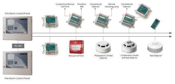
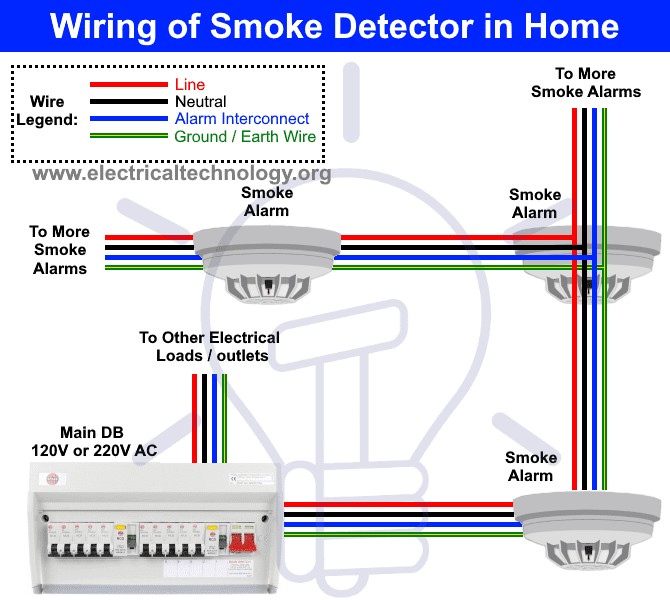
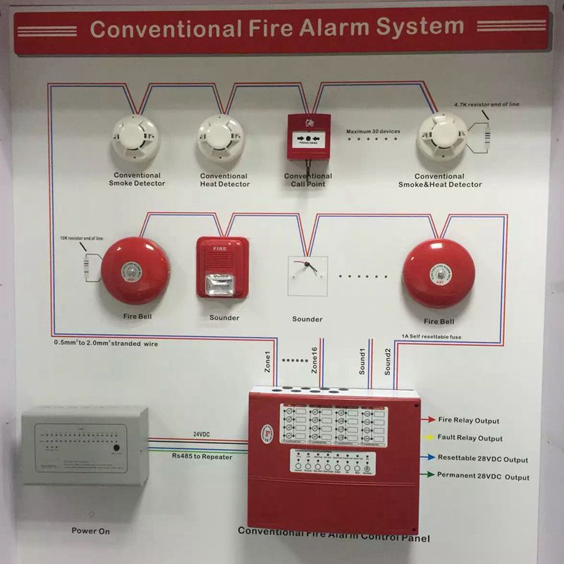
Addressable smoke detector wiring diagram. The smoke detectors wiring harness has two parts. It reveals the elements of the circuit as simplified shapes as well as the power and signal connections between the gadgets. This is the basic fire alarm system used in household wiring. Remove power from the communication line before installing sensors. A smoke or heat detector can be installed to the existing or new home wiring. A wiring diagram is a simplified standard photographic depiction of an electric circuit.
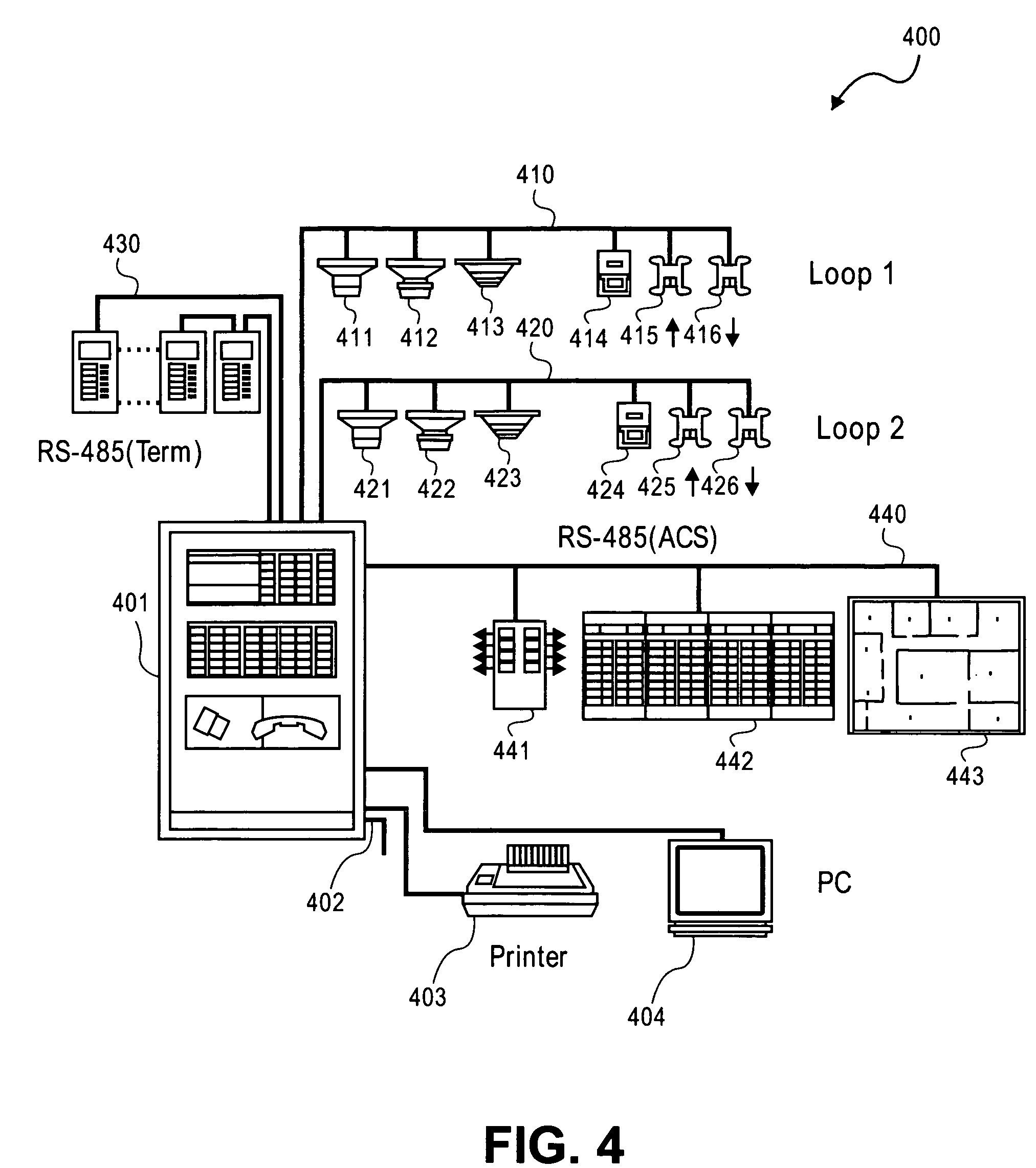
Variety of addressable fire alarm system wiring diagram. How to wire to a conventional or addressable fire panel. Conventional addressable and analogaddressable fire alarm systems are also presented. B wiring diagram for ms msls msudls msud msudls. There are two types of fire panels conventional types which have zones which are connected directly to devices such as optical beam smoke detectors or flame detectors and analogue addressable types which have a loop bus onto which addressable devices can be connected. Conventional wiring features the 5192 series smoke detectors are designed to provide open area coverage and are well suited for most fire detection applications.
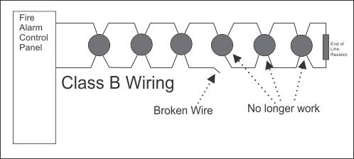
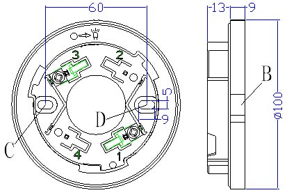
Two type of fire alarm detection system 1 addressable system 2conventional system modernexpe. Know the basics of smoke detector wiring and learn how these detectors are connected together in a series. White black and yellow. The detector operating mode is selected using the mode switch situated on the rear of the unit. System wiring explains the differences between slc class a and class b circuit wiring use of. Wire the sensor base supplied separately per the wiring diagram see figure 1.
In our basic wiring diagram a single or multiple heat and smoke detectors are installed in the home by connecting the live line or hot neutral ground and an interconnected wire to the alarm. It can be accessed by sliding a. You should be able to see three wires coming out of the harness. The fixed wires and the wires that protrude from the harness. Here i show the layout diagram of fire alarm detection system. Be color coded to limit wiring mistakes and ease system troubleshooting.
Detector zone wiring see note 1 fire relay trouble relay 102 to 30 volts dc red 0v black psu. An automatic fire alarm systemtypically made up of smoke wiring a style y nac two wire with addressable control modules. Im proper connections will prevent a system from responding properly in the event of a fire.
Gallery of Addressable Smoke Detector Wiring Diagram