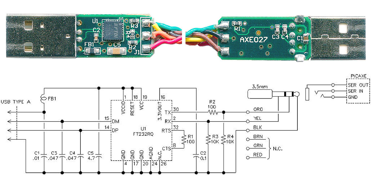
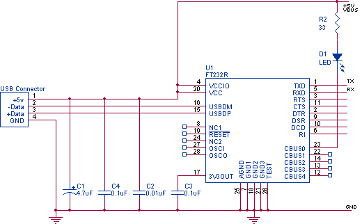
The chip handles all the protocol of converting usb data to uart serial data. I decided to rip the plastic off the db9 and discovered a really tiny pcb.
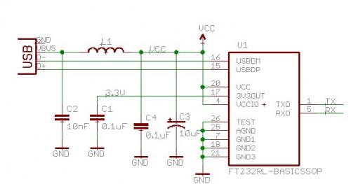
Eagle Schematics Dxarts University Of Washington
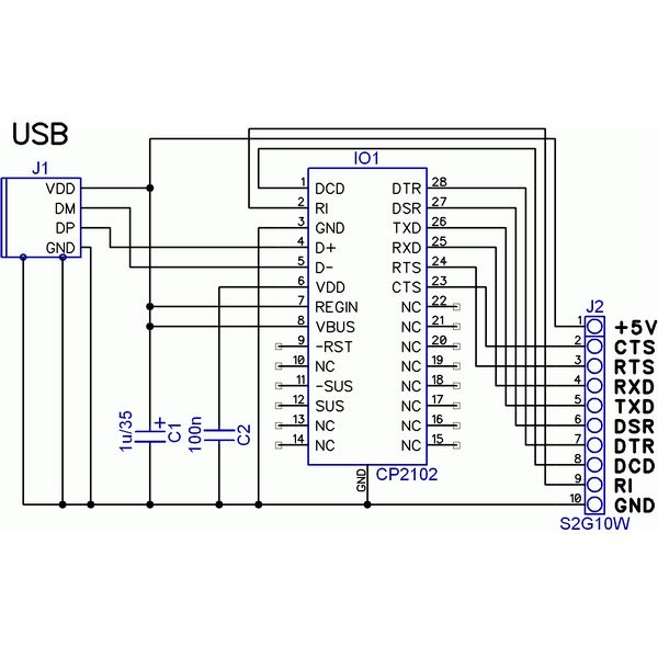
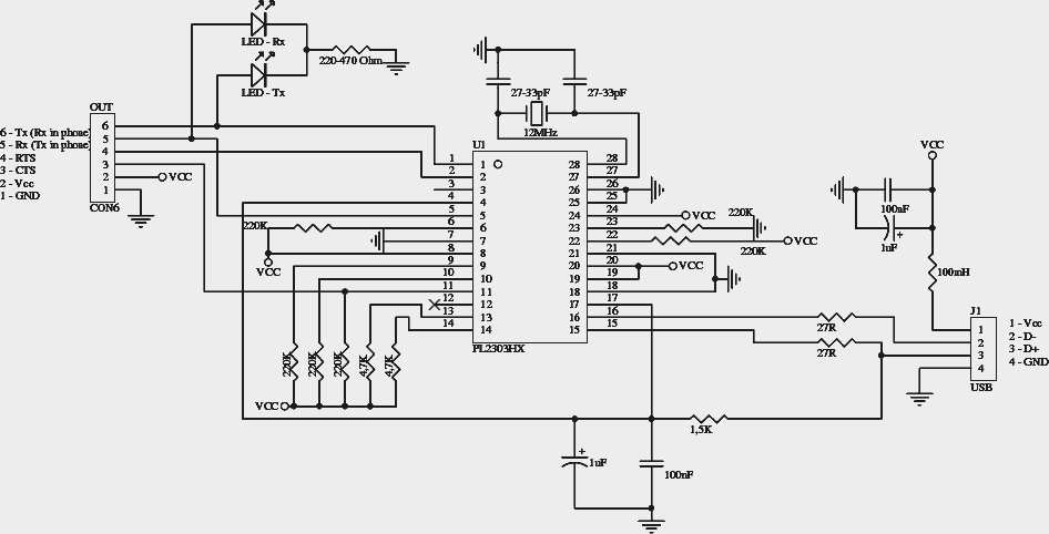
Usb to ttl wiring diagram. According to adafruit ttl serial to usb wiring diagram you will find just four wires used from the cable. 70 1795. However its inherently limited in many aspects as its not a full usb port and it cant replace a real usb hardware in many applications. Usb to ttl converters are required for interfacing microcontrollers to pc it is also required for loading code in arduino mini settingmodifying esp8266 firmware. But if you need a moderately low speed usb communication then go for it. Lots of usb to ttl modules are available in the market based on various chips like pl2303.
The data is transferred through the d and d connectors while vbus and gnd connectors provide power to the usb device. As shown in ftdi cable pin diagram one end of ftdi cable is connected to usb and other end we have six. Black wire serves as floor just like in any other apparatus. 954 the cable is easiest way ever to connect to your microcontrollerraspberry piwifi router serial console port. Typically it utilizes black black red and white wire colors. The red one is for sure wire with dc power of 5 volts.
35mm audio jack 2 core and spiral 24 awg diam5mm ttl 232r 3v3 aj usb to uart cable with 33v ttl level uart signals. Ftdi cables are the family of usb to ttl serial uart converter cables and they are incorporated with ft232r ic. Ftdi cable usb to rs232 converter pinout. See also ftdi serial ttl 232 usb cable id. Usb a b 20 and 30 cable pinout. Ttl 232r 3v3 we usb to uart cable with 33v ttl level uart signals.
Wire ended no connector 6 core ul2464 24 awg diam5mm ttl 232r 5v aj usb to uart cable with 5v ttl level uart signals. One of the most common way to interface a microcontroler to a computer used to be serial port. Adafruit industries unique fun diy electronics and kits usb to ttl serial cable debug console cable for raspberry pi id. Wiring flashing programming esp 32 esp32s with usb ttl uart and integration with arduino ide esp32s wifi bluetooth combo module is ultra performance that is high ultra low power consumption wi fi and bluetooth wireless platform based on espressif esp32 chipset. Usb to ttl serial cable debug console cable for raspberry pi id adafruit ttl serial to usb wiring diagram uploaded by yamama on monday february 11th 2019 in category usb wiring diagram. The usb ttl converter provides a very good yet easy to run solution for adding usb connectivity for your project.
The usb cable provides four pathways two power conductors and two twisted signal conductors. A common way to fix this issue is to use a usb to ttl converter or a usb to rs232 converter max232. Over here we are going to make a do it yourself diy usb to ttl module on a breadboard. But right now serial port have been replaced with usb on most computers. The usb device that uses full speed bandwidth devices must have a twisted pair d and d conductors. 35mm audio jack 2 core and.
Inside the big usb plug is a usb serial conversion chip and at the end of the 36 cable are four wire red power black ground white rx into usb.


