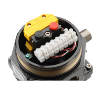
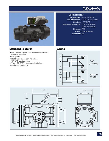
Wiring diagrams are supplied with each specific switch box configuration dependant on specification. Wiring diagrams 2 off 2 wire inductive sensor cs transmitter 10pt ts wiring diagrams.
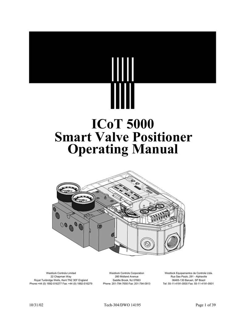
Westlock Controls Corporation Beacon Specifications Manualzz
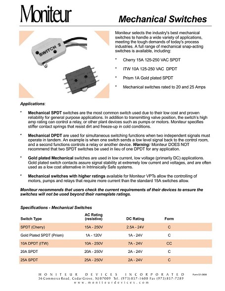
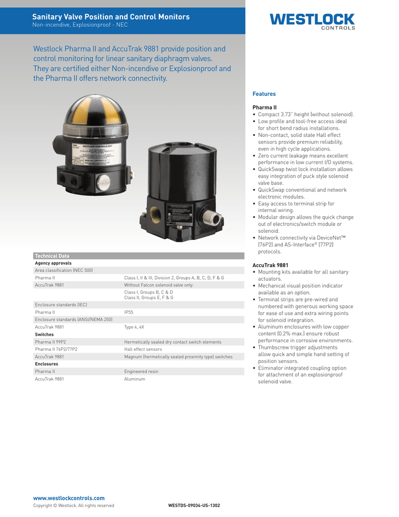
Westlock limit switch wiring diagram. Rotary linear general purpose. Ip rated plugs prevent ingress during site storage and. Westlock valves controls home. The accutrak family of products offers an integrated solution for the monitoring of process valves by combining switchessensors wiring terminals enclosures and local visual indication in one compact unit. Product product line valve type classification standards. Quality mechanical switches roller arm.
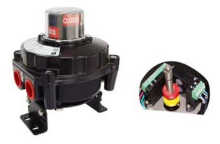
Wiring options for 7644 7679d 7679 me or xe are shown in fig. Westlock controls has built a global reputation providing innovative solutions for networking monitoring and controlling process valves. Soldered and sheathed wires. All wiring must be in accordance with national electrical code ansi nfpa 70 for area. Ip66 abs enclosure provides high strength and corrosion resistance. Certificates approvals and qualifications accutrak position monitors 22002300260030003200330034003500830084008500 sil3 cerrtification.
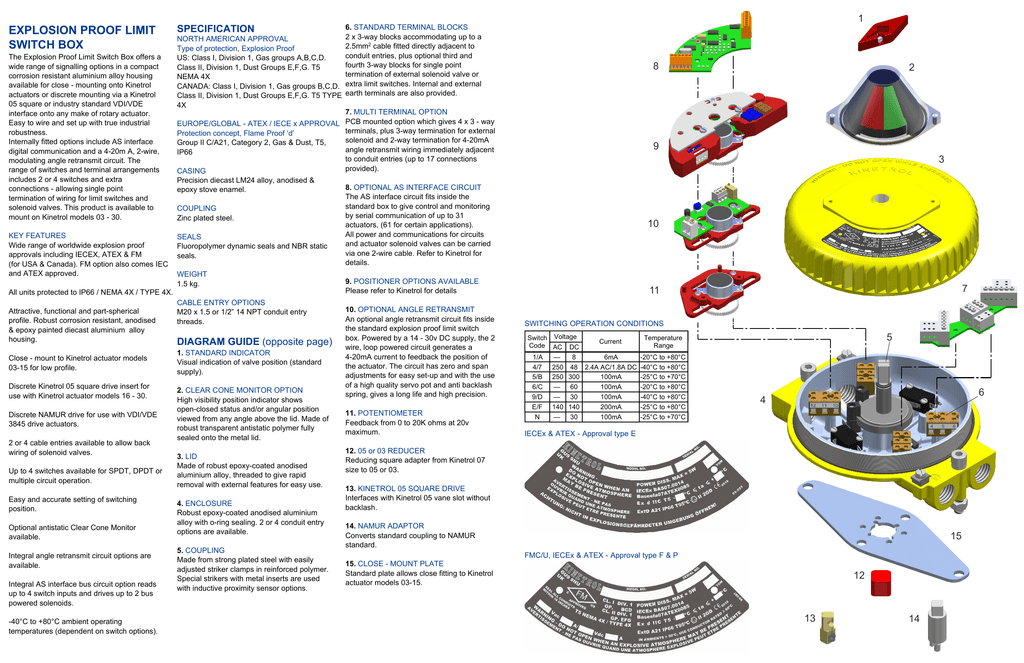
Our focus on technology and supplying reliable products manufactured to the highest industry standards makes us a preferred choice with the worlds leading process companies and a trusted partner for developing even. Limit switches sensors. A selection of standard configuration wiring diagrams are available for our most popular switches and sensors. Accutrak silver bullet position sensor atexiec. Centralization plate allows accurate switch setting improves repeatability and minimizes hysteresis. Our support library contains a range of documents and reports which have useful and relevant information specifically about the monitoring and control of process control valves.
Westlock intellis 7644 7679 me or xed 7679 me or xe field wiring instructions 1. Quantum wiring diagrams 1 2 3 4 5 6 7 8 brown purple yellow nc no c orange blue red nc no c switch 1 upper switch 2 lower falcon solenoid green ground 1 2 3 4 5 6. The proper wiring diagram for your unit is shown on the inside of the 7679me or xe covers. Quick release terminal strip aids wiring. Download e mail document.

