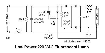
The choke is in fact a large. The starter is like a key of fluorescent light because it is used to light up the tube.
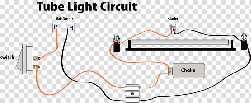
Wiring Diagram Fluorescent Lamp Circuit Diagram Choke
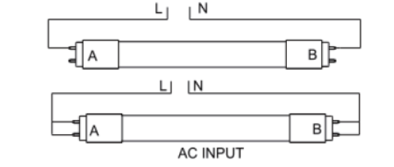
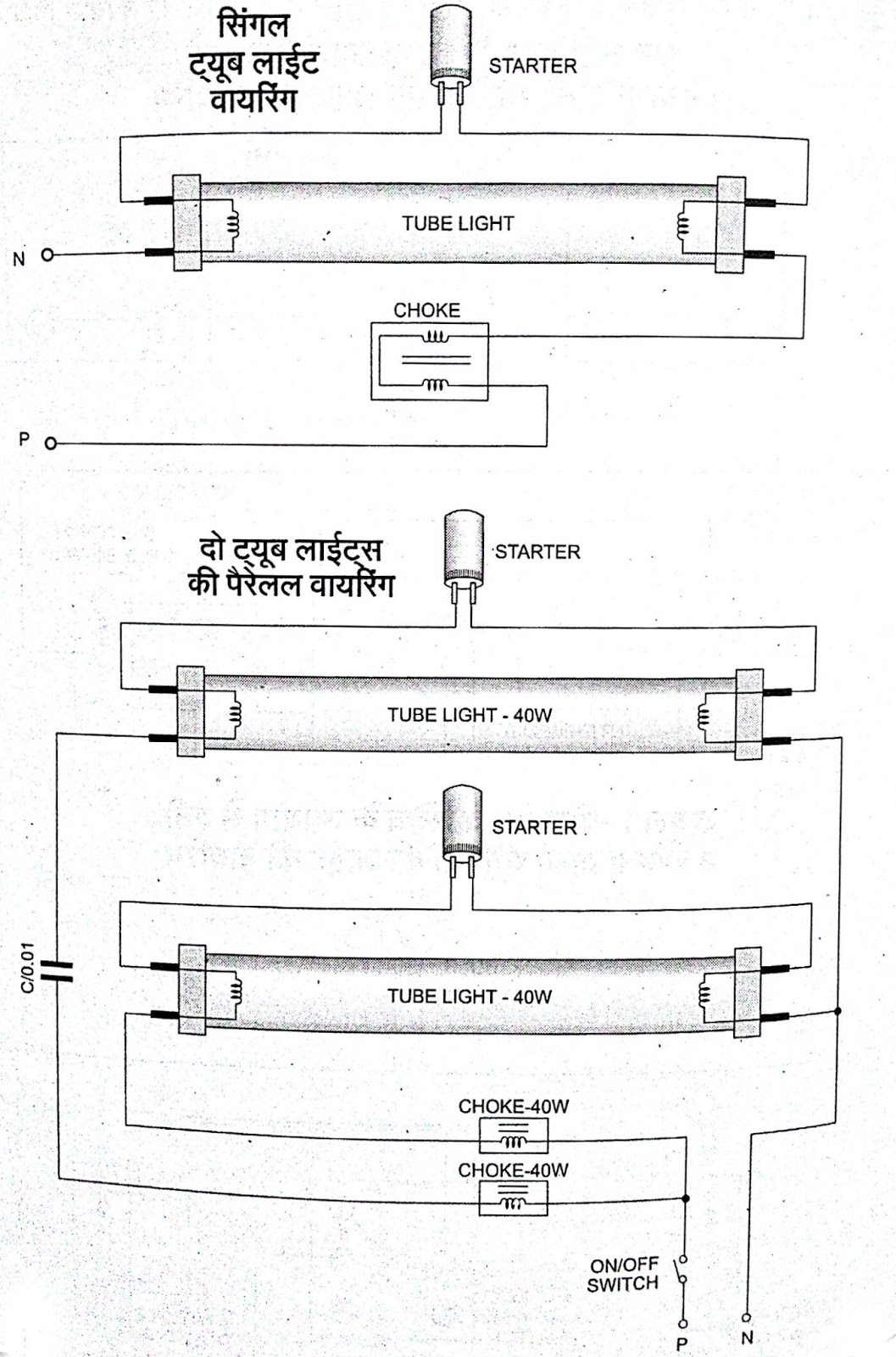
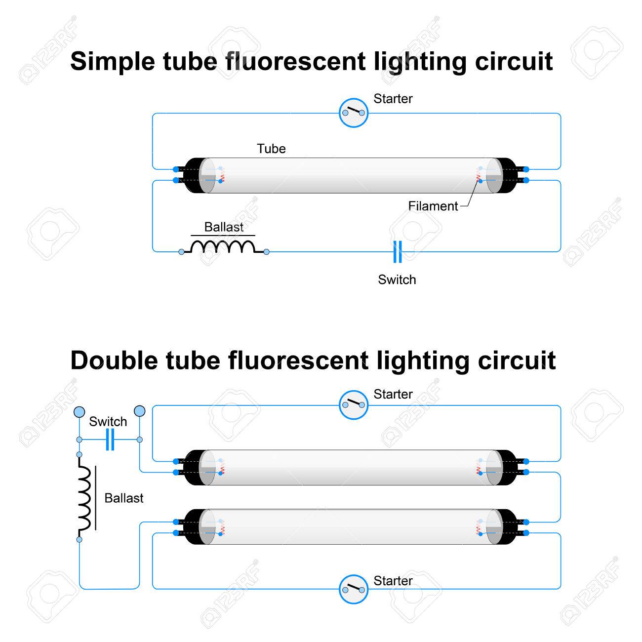
Tube light choke wiring diagram. One end of a starter is connected to pin 2 of terminal 1 and another end of the starter is connected to the pin 2 of terminal 2. Two tube with one ballast choke wiring diagram here in this tube light wiring diagram you will find two fluorescent tubes are connected with one choke or ballast two separate starters are used for each tube and finally connected to 230v power supply through a switch. It shows the parts of the circuit as streamlined forms and also the power and signal connections between the gadgets. Tube light connection of electrical choke tube light connection of electronic choke tube light connection of led my other videos house wiring of main electrical board step by. Assortment of t8 led tube light wiring diagram. A magnetic ballast also called a choke contains a coil of copper wire.
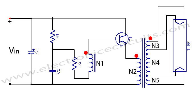
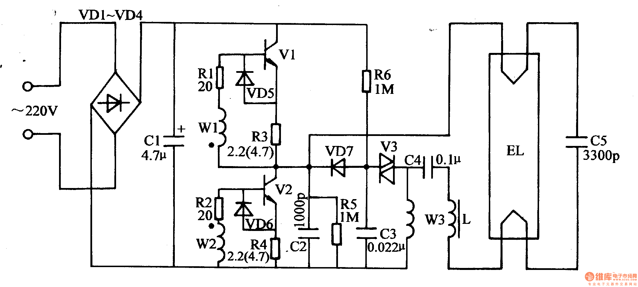
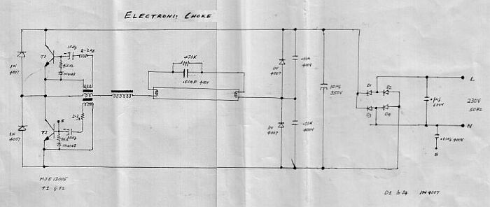
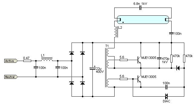
Wiring diagram of single tube light installation with electronic ballast. One terminal of choke or ballast is connected to port 1 and another terminal is connected to pin 1 of terminal 1. That amount can fluctuate depending on the thickness and length of the copper wire. The function of choke is to provide high voltage enough for ionization to take place in a tube light and after establishment and substenance of ionization limit the voltage across the tube. This article gives a details about double tube light connection by using single ballast or choke some electronic choke not support this connection check the ballast specification and watts level before make this type of connection. Please refer to the circuit diagram on the right as you read the following points.
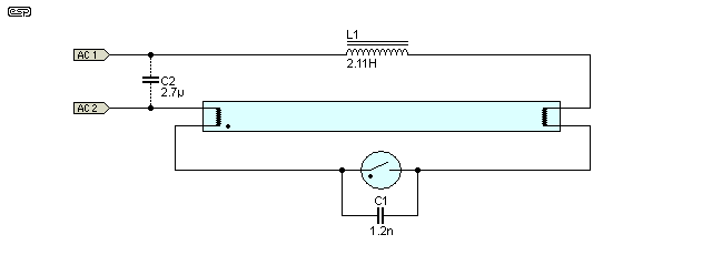
When we connect the ac supply voltage to the circuit then the starter act like short circuited and current flow through those filament located at the first and second end of the tube light and the filament generate heat and it ionized the gas mercury vapor in the fluorescent tube lamp. Wiring of flourescent lights. Here is one example of a tube light fixture consisting of a large heavy square choke or ballast and a small cylindrical starter lets try to understand how the whole system works. The tube light or fluorescent light is a low pressure mercury vapor gas discharge lamp and it uses fluorescent to produce white light. Schematic wiring diagram for two tube light with one ballast choke. The magnetic field produced by the wire traps most of the current so only the right amount gets through to the fluorescent light.
Tube light wiring diagram. A wiring diagram is a simplified standard pictorial representation of an electrical circuit. We need tube light ballast starter and fluorescent light holders to make wiring connection. Wiring diagram here two tube lights are used in our case each one is 20 watts each tube light will have.
