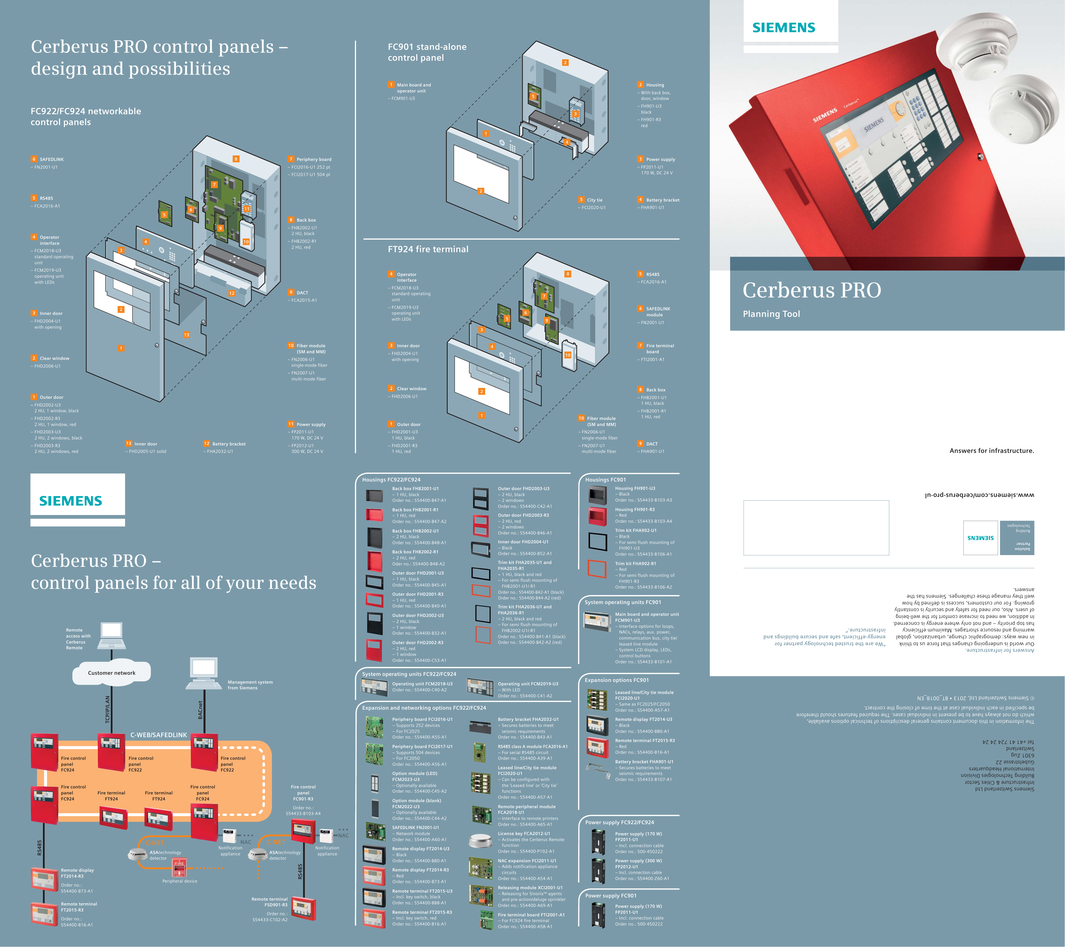
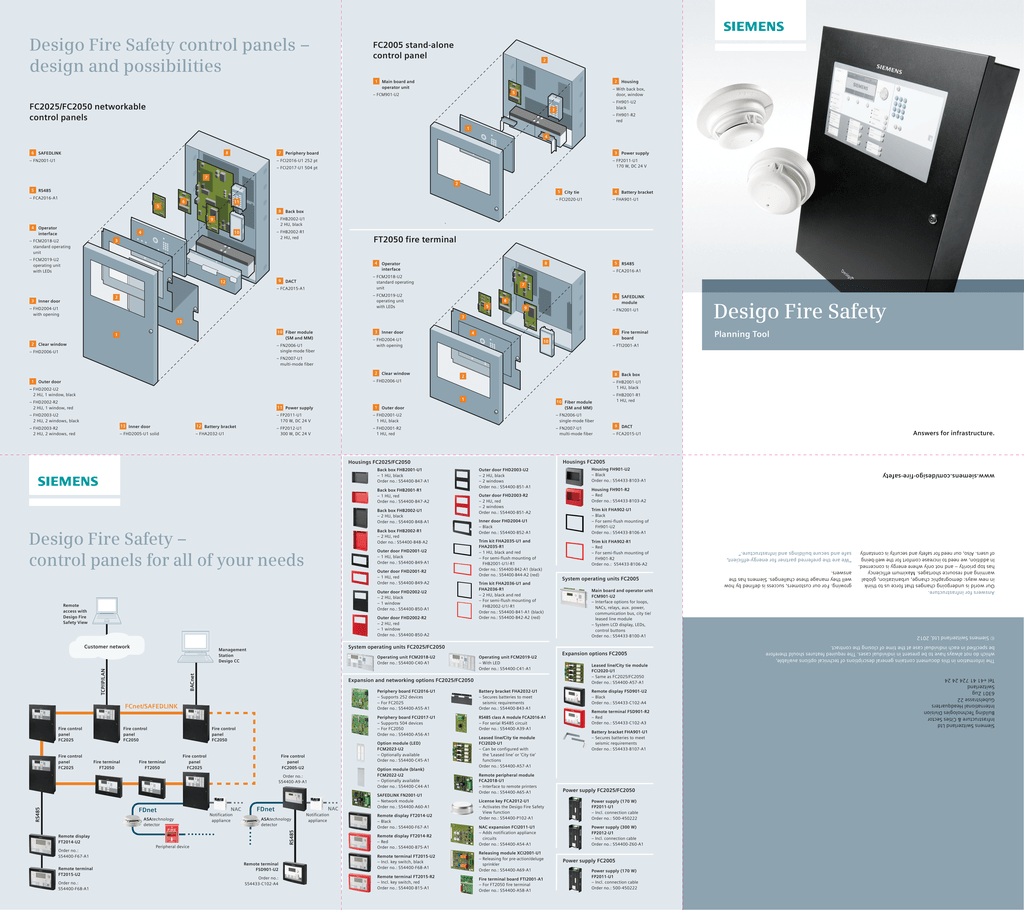
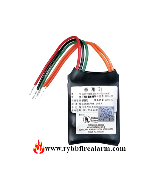
Pn 315 034904 4 building technologies division operation the model hlim loop isolator module from siemens industry inc. The 24 vdc power may be wired only as class b.

Frontiers The Musical Structure Of Time In The Brain
Siemens hcp module wiring diagram. The siemens mode htri series intelligent interface. Page 3 nec 760. Module incorporates a microcomputer chip and each interface module achieves the state of an intelligent device through its microcomputer chip technology combined with its sophisticated bi directional communication capabilities with the fa cp. Analog input module ai 4xrtdtc 2 3 4 wire hf 6es7134 6jd00 0ca1 4 equipment manual 092019 a5e03573289 af. I need wiring diagram to connect 2 wire and 4 wire transducer to analog input module for the following cases. Siemens fires nac series of alarm signaling devices.
Figure 2 shows the class a wiring. Deari need to verify the wiring of 6es7321 1bl00 0aa06es7322 1hh01 0aa06es7331 7kf02 0ab0i have prepared wiring diagrams for these above modules. Since the hzm monitors the power at its screw terminals you can star or t tap the power connection. Pn 315 034850 8 building technologies division. Refer to figure 7 for the wiring diagram. 2 wire transducer to 2 wire module 2.
4 wire transducer to 2 wire module 4. The step 7 online help supports you in the configuration and programming. Additionally various siemens fire safety facps which include siemens modular as well as the 50 point 252 point and 504 point addressable facps can recognize model hcp devices. Device information product manuals contain a compact description of the module specific information such as properties wiring diagrams characteristics and technical specifications. Model hcp z can be configured as an independent remotely located telephone zone speaker zone or. Wiring and commissioning of the simatic s7 1500 and et 200mp systems.
Wiring should be connected to the nac circuits on the main board or the auxiliary power supply on the pad 4. Wiring should be connected to tb3 on the psc 12 and psx 12 or the auxiliary power supply on the pad 4. For fs 250 systems the hcp is powered by the nac circuits and pad 4. Hzm is a polarity insensitive module and terminals 1 and 2 can be connected to either line of the dlc or fs dlc device loop. Hzm initiating devices wiring diagram class a style d installation figure 3 hzm initiating devices wiring diagram. Siemens provides products and solutions with industrial security functions that support the secure operation of plants systems machines and networks.
Isolates short circuits on firefinder xls or fs 250 analog loops. I m new to control field. 2 wire transducer to 4 wire module 3. By placing devices between hlims during installation a short in the wiring within that group is disconnected from the rest of the loop. Please find attached wiring diagram and suggest any correction in itthanks. 4 wire transducer to 4 wire module i am a bit confused about m m and mana.
Page 6 electrical ratings i t i l i f l l u siemens industry inc.

