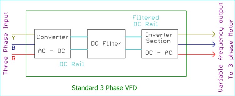
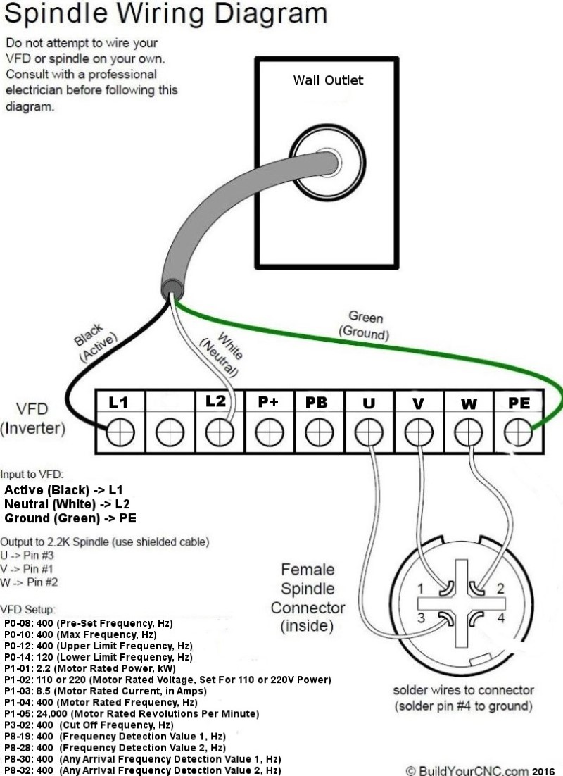
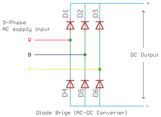
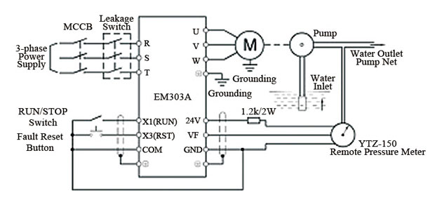
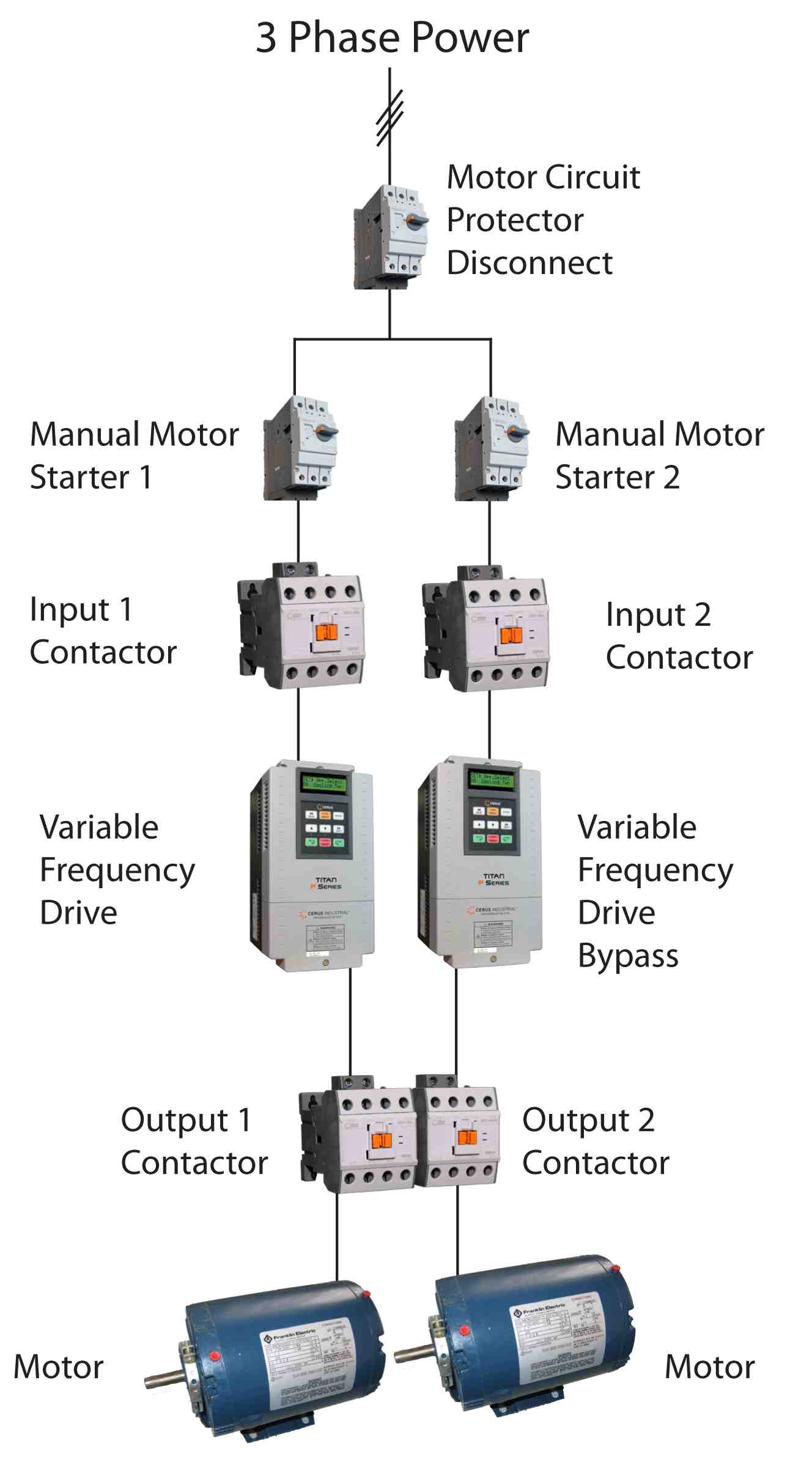
1 the vfds three phase ac input terminals rl1 sl2 tl3 the power lines input terminals connect to 3 phase ac power through line protection or leakage protection breaker it does not need to consider the connection of phase sequence. Run wires 3 power wires and 1 ground wire from your breaker panel to your vfd.

Single Phase Variable Frequency Drive Vfd Circuit Circuit
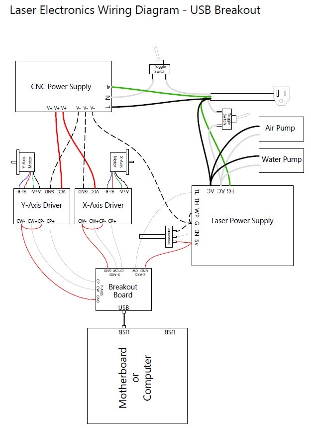
Vfd panel wiring diagram. Then as per vfd logic if dl 1digital logic goes high vfd start to feed the output voltage motor start rotating. It shows the parts of the circuit as simplified shapes as well as the power as well as signal connections in between the tools. Wellborn assortment of vfd panel wiring diagram. K1 no1 pb3 pb4 pb5 should be of potential free contact. Variety of vfd panel wiring diagram. Vfd panel wiring diagram sample.
A wiring diagram is a simplified standard photographic depiction of an electric circuit. Run wires 3 power wires and 1 ground wire from your breaker panel to your vfd. Motor will be stopped. Make sure your power wire is rated for the full load amps 14 gage wiring up to 15 amps 12 gage up to 20 amps 10 gage wire up to 30 amps 8 gage wire up to 40 amps 6 gage wire up to 50 amps 4 gage wire up to 70 amps 2 gage wire up to 100 amps and. Vfd start stop wiring diagram. Abb vfd wiring diagram reference square d vfd wiring diagram free vfd wiring diagram wiring diagram includes several in depth illustrations that present the link of varied products.
Then k1 no1 become no vfd stop output voltage. Make sure your power wire is rated for the full load amps 14 gage wiring up to 15 amps 12 gage up to 20 amps 10 gage wire up to 30 amps 8 gage wire up to 40 amps 6 gage wire up to 50 amps 4 gage wire up to 70 amps 2 gage wire up to 100 amps and. A wiring diagram is a streamlined conventional photographic depiction of an electrical circuit. A wiring diagram is a simplified conventional pictorial representation of an electric circuit. It reveals the parts of the circuit as simplified shapes and the power and signal connections in between the tools. Posted on march 18 2018.
When you press the on push k1 contactor will hold and k1 no1 become nc. It shows the parts of the circuit as streamlined forms and the power and also signal links between the gadgets. Main circuit wiring the vfd main circuit terminals shown as below figure. When you press stop push button 2 then k1 contactor get release. December 5 2018 by larry a. Assortment of vfd wiring diagram.
Connect or do wiring as per vfd side drawing you take 24 v from the vfd pcb directly. It contains guidelines and diagrams for different varieties of wiring strategies and other items like lights home windows and so forth.




.png)
