At the top edge. Pairing the st621tx to boiler module receiver.

Salus Rt10 24v Underfloor Thermostat
Salus rt310rf wiring diagram. 44 0 1226 323961. Pairing rt510rfrt510tx to the receiver post october 2018. Page 6 receiver terminals switch terminal common switch terminal mains live 230vac mains neutral wiring electrical diagram wall mounting fix the backplate to the wall align the front housing fit the front housing. The thermostat provides the user interface and temperature sensing control. The two units are linked together by a radio frequency rf signal. Blue n brown no orange hw call c grey hw l e yellowgreen n hw motorised valve model nosspsbmv22 sbmv28 ac mains in nc hws no hw ch 12 13 15 14 11 10 9 8.
Salus controls plc salus house dodworth business park south whinby road dodworth barnsley s75 3sp uk. The rt310rf from salus controls is a stylish and accurate digital thermostat with an easy to read liquid crystal display lcd. Rt310 wiring diagram rt310rf wiring diagram rt310 rt310tx thermostat supply 2 x aa alkaline batteries 2 x aa alkaline batteries receiver supply 230 v ac. Accepts no liability for any loss or damage arising from any errors or omissions that may be inadvertently contained within this diagram. Press lightly 06 rt310rf installation manual. Articles in this section.
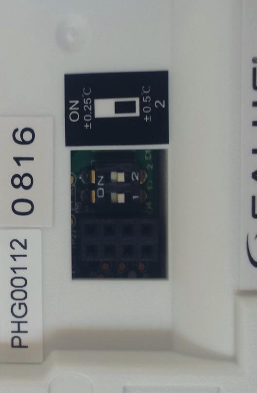
We have improved the test pairing on the rt310rf thermostat on models produced after 1018 october 2018. You can check the date by looking for a small sticker with 4 digits on the back of the thermostat. Please follow the new procedure below. The rt310rf is factory pre paired as standard. The receiver is used for wiring connections and heat on off control.
