B check control wiring. 4142014 102702 am.

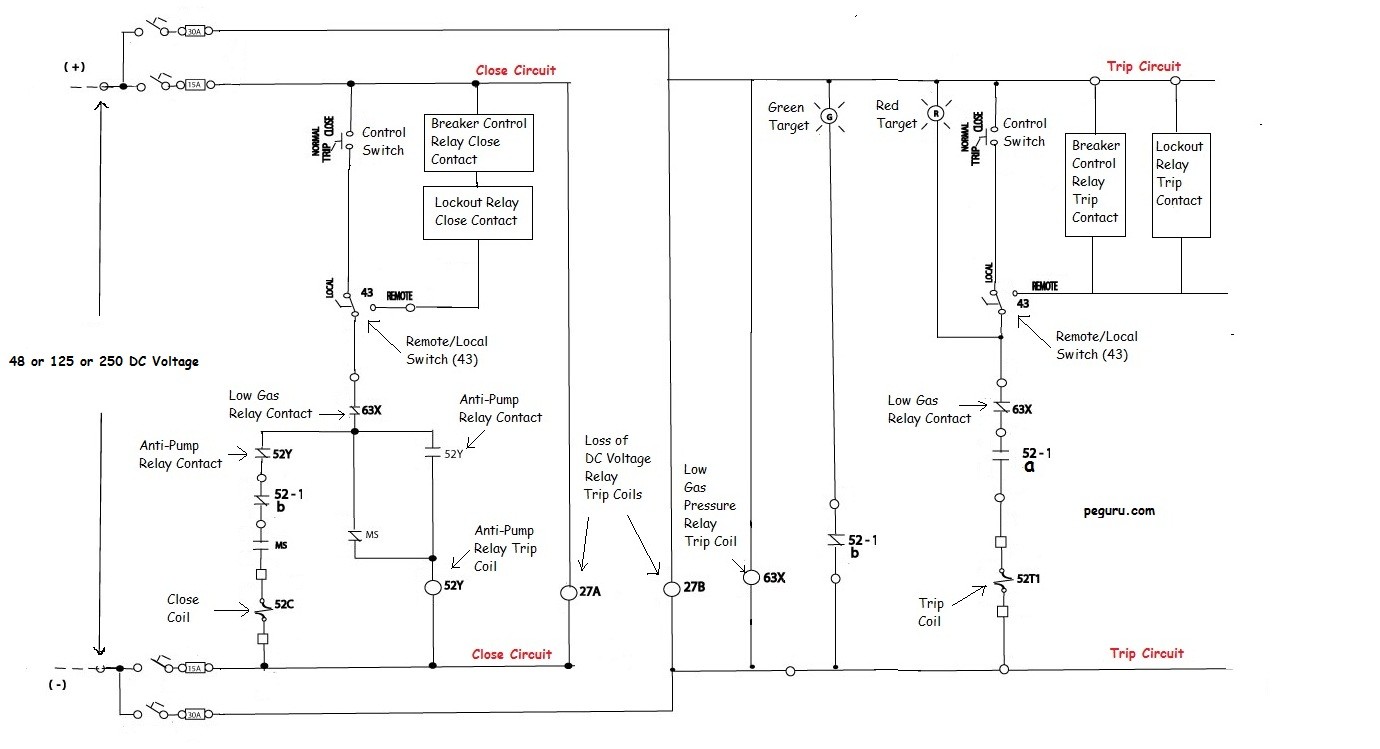
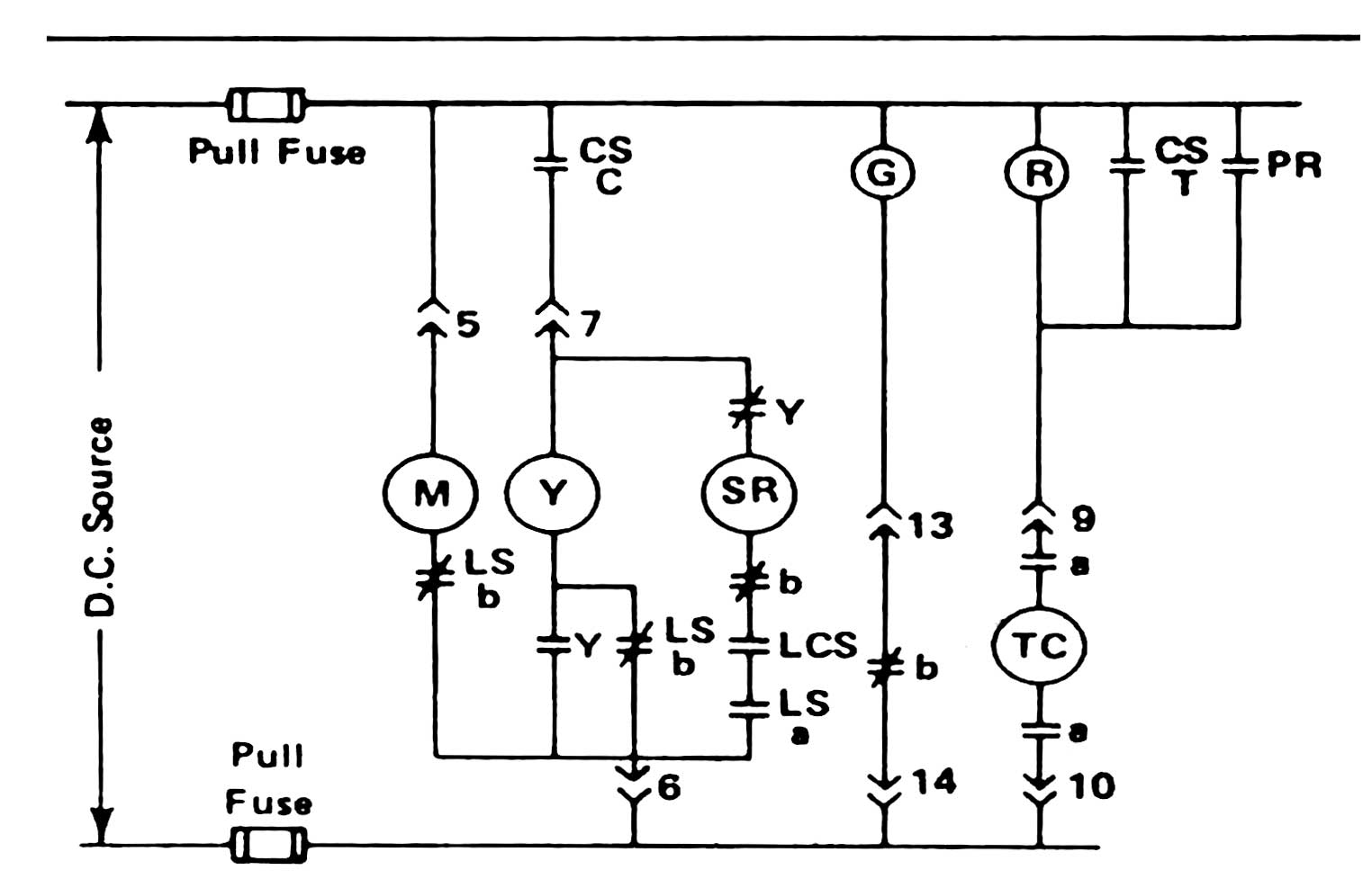
Standard Tripping Schemes And Trip Circuit Supervision
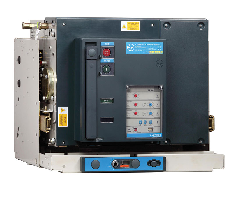
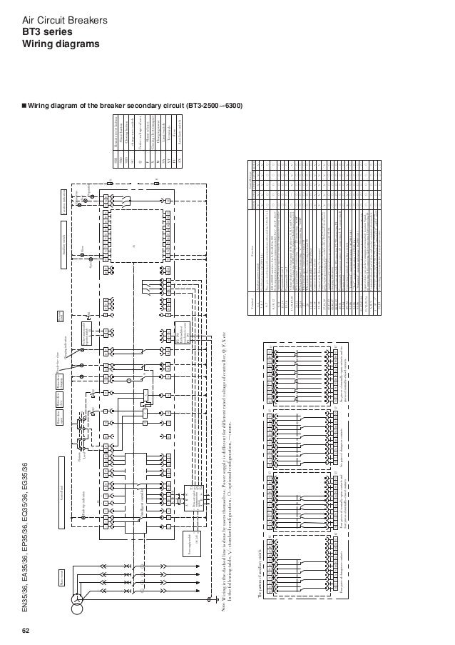
Acb control wiring diagram pdf. Air circuit breaker acb air circuit breaker acb is an electrical protection device used for short circuit and overcurrent protection up to 15kv with amperes rating of 800a to 10ka. For more details refer to the wiring diagrams of the product. It operates in air where air blast as an arc quenching medium at atmospheric pressure to protect the connected electric circuits. Typical starter wiring diagram three phase. The control circuit may not be at the same voltage as the power circuit. If the volt ages are different it is called separate control.
The bendix wingman acb system will give up to 30 seconds warning to the driver when approaching in your lane of travel sizable stationary objects with reflective surfaces. The soa is active whenever the vehicle is moving whether or not cruise control is engaged he driver should be especially careful when approaching certain t. Control wiring diagram 26290002dgn. Check control wiring of shunt release ensure that shunt release gets supply. The npl loads are always combined with line ln1. Configuring the unit without a priority line or with ln2 as the priority line does not change the way changeover of cb3 is managed.
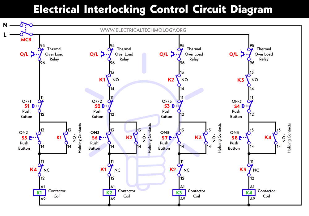
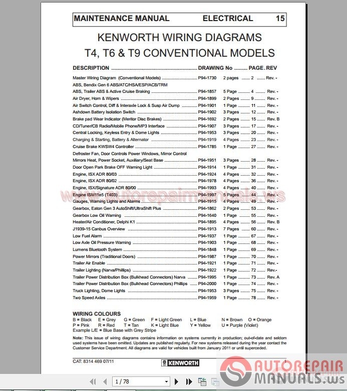
D latch of the mechanism spring not. Wiring diagram book a1 15 b1 b2 16 18 b3 a2 b1 b3 15 supply voltage 16 18 l m h 2 levels b2 l1 f u 1 460 v f u 2 l2 l3 gnd h1 h3 h2 h4 f u 3 x1a f u 4 f u 5 x2a r power on. 18 gauge standard single thermostat standard ac condenser ac contactor control board standard air handler 3 this diagram is to be used as reference for the low voltage control wiring of your heating and ac system. Wiring diagram index name description page aa power distribution frc 12 3 ab power distribution frc 22 4. Ag vehicle ecu 13 ems power control 9 ah vehicle ecu 23 10 ai vehicle ecu 33 11 aj vecu and pto switches 12 am starting charging isx g with in frame 13. The control circuit is separate from the motor circuit.
26290002 control wiring diagram default created date. Always refer to your thermostat or equipment installation guides to verify proper wiring. Control board standard air handler 3 this diagram is to be used as reference for the low voltage control wiring of your heating and ac system. Always refer to your thermostat or equipment installation guides to verify proper wiring. Note some ac systems will have a blue wire with a pink stripe in place of the yellow or y wire. Control wiring wire size.
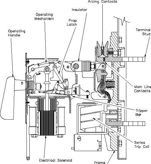
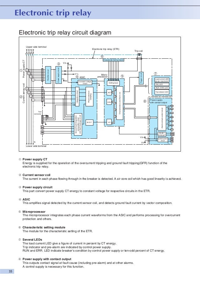
When the voltage of the control and power circuits is the same it is referred to as common control. Internal wiring diagram of new dn release ct r phase ct y phase ct b phase t1 m1 t2 m2 t1 m1 t2 m2 t2 m1 t2 m2 s o l. From acb but trip bar of release kept free. Typical controller markings typical elementary diagram table 4 control and power connections for across the line starters 600 v or less from nema standard ics 2 321a60.
