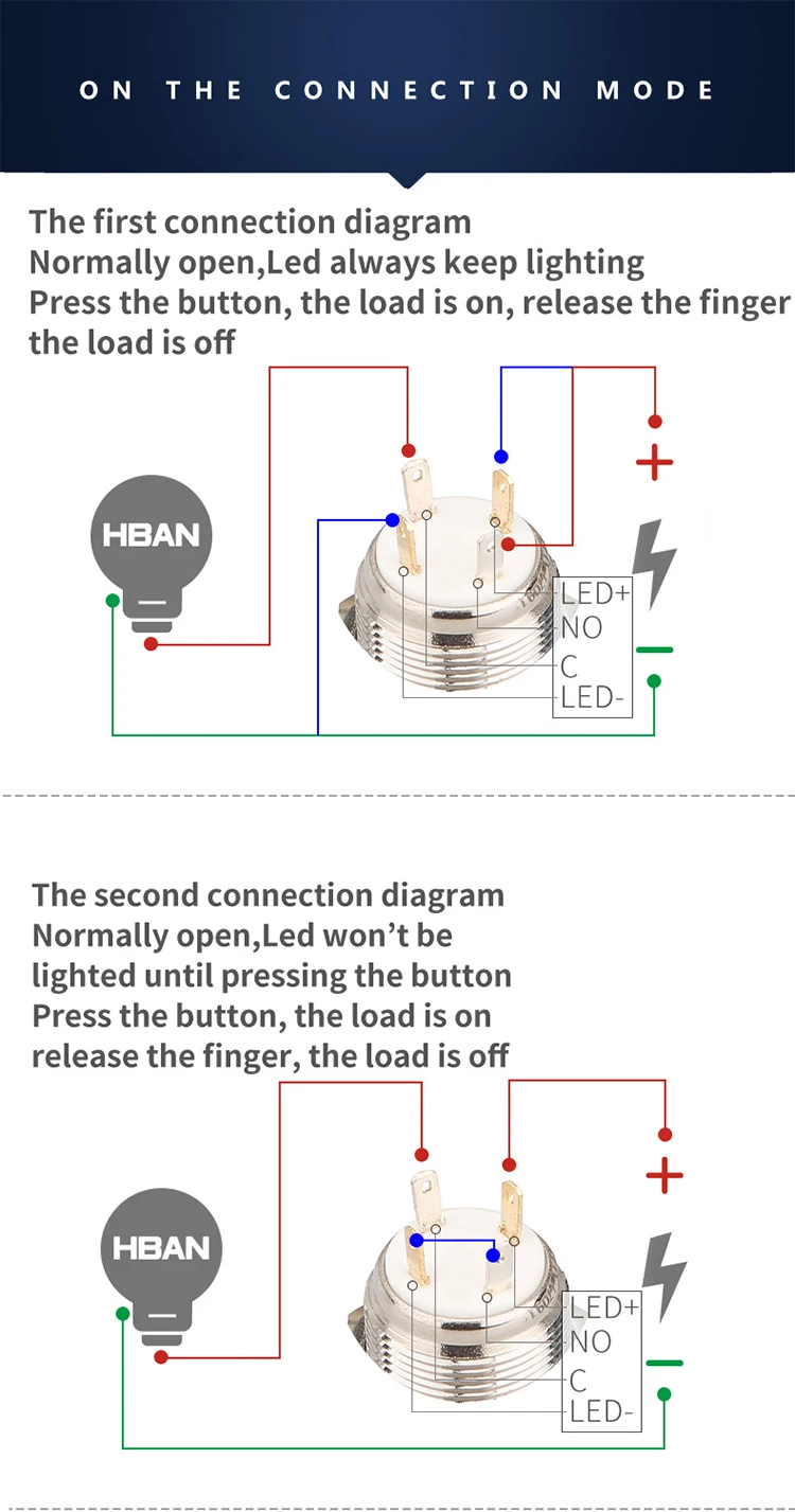
We customize the button to your liking and have a lot of pre. Simple wiring for toggle switch and push button start duration.

Black Push Button Switch 4 Pin 12mm Waterproof Led Light Metal Flat Momentary Latching Switches With Power Mark Ring Led
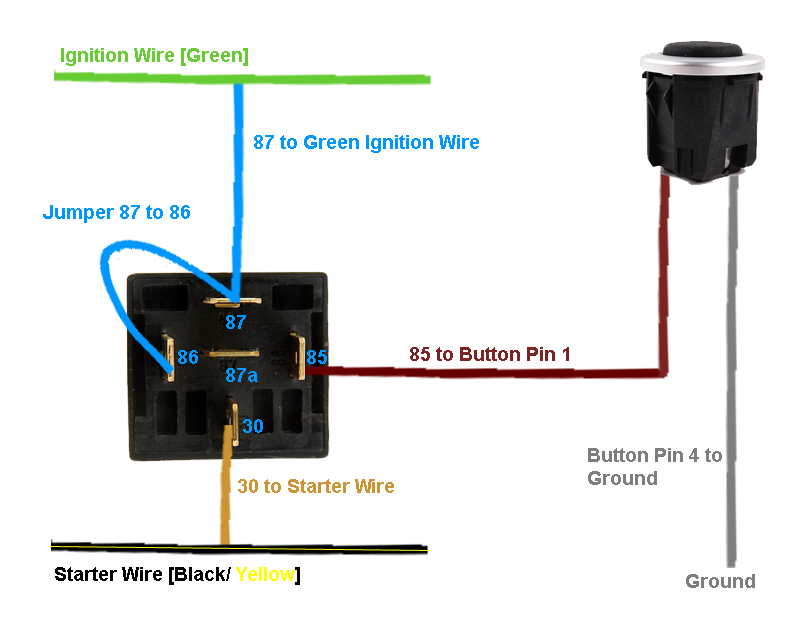
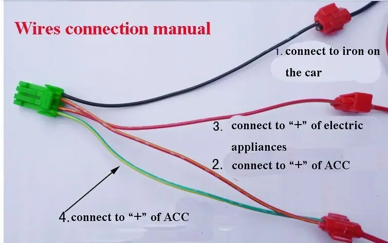
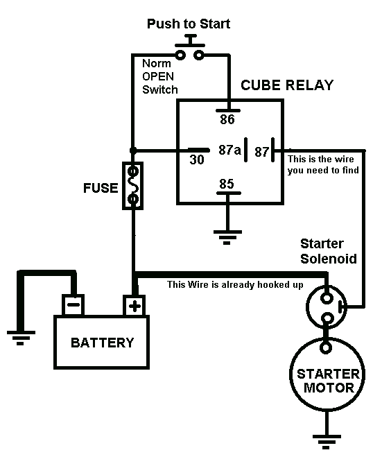
Push button wiring diagram. Push button starter switch wiring diagram circuit using 11n push button starter switch wiring diagram. Push button starter switch wiring diagram push button ignition switch wiring diagram push button start switch wiring diagram push button starter switch wiring diagram every electrical arrangement consists of various distinct parts. Heres a fun project that i did to my very first car. Almost all industrial machines contain push buttons even if the facilities operation is to set to run automatically. It contains instructions and diagrams for various kinds of wiring techniques and other things like lights home windows and so forth. We send a card with these diagram with every order.
Fiber optic cable electrical connections boundary seal to be in accordance with article 501 5 of the national. The first two red and black connect to the two long vertical rows on the side of the breadboard to provide access to the 5 volt supply and ground. Typical push buttons are momentary meaning they are designed with a spring to keep the button contacts open or closed at all times. Each component ought to be placed and linked to other parts in specific manner. Wiring diagram contains numerous comprehensive illustrations that show the relationship of varied items. That same leg of the button connects through a pull down resistor here 10k ohm to ground.
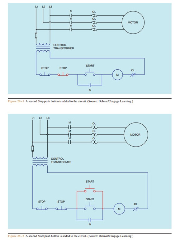
Cbb is your source in north america for custom laser etched billet push button for your car boat offroad rig sled racing simulator cnc machine or just about anything that you can control with a push button. Push buttons shown in figure 1 are the most common type of control devices found in industrial facilities. The third wire goes from digital pin 2 to one leg of the pushbutton. Awesome push button ignition. Typical wiring diagrams for push button control stations 3 genera information at each circuit is illustrated with a control circuit continued schematic or line diagram and a control station wiring diagram. Connect three wires to the board.
Wrench and rides 207967 views. Wiring diagrams 55 57 type s ac combination magnetic starters58 59 class 8538 and 8539 58 59 3 phase size 0 5 58. Push button selector switch limit switch etc. L the schematic or line diagram includes all the components of the control circuit and indicates their. Otherwise the arrangement wont work as it ought to be. When i first got it i was quite happy with my purchase but soon after that i found that i really wanted a sweet push button ignition and an engine kill switch like a rocket or a race car or s.
Gy6 electrical troubleshooting tutorial no spark eliminator duration.


