Published on jun 15 2020. Please try again later.

Platinum Remote Pcb Diagram Electronic Engineering
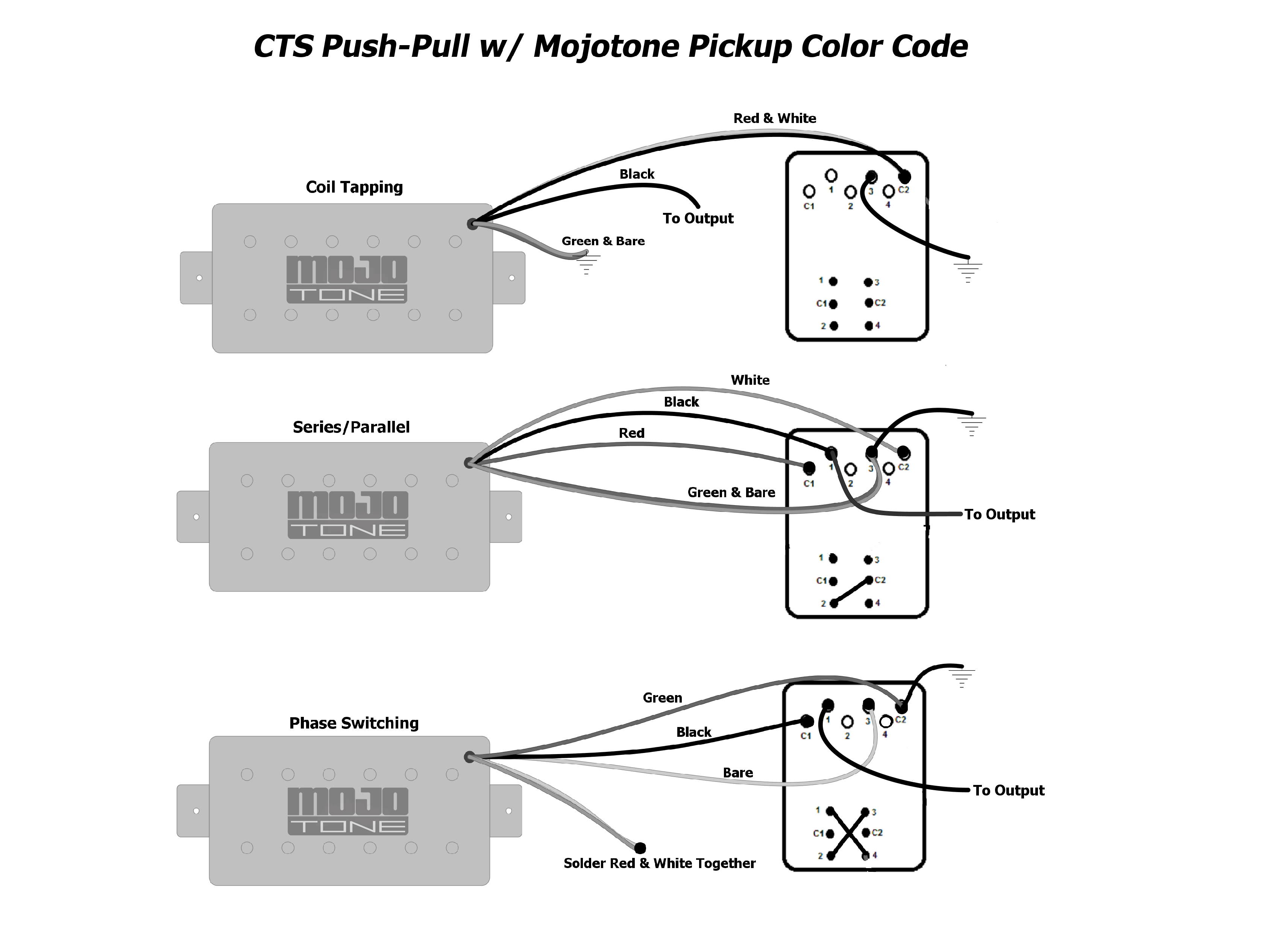
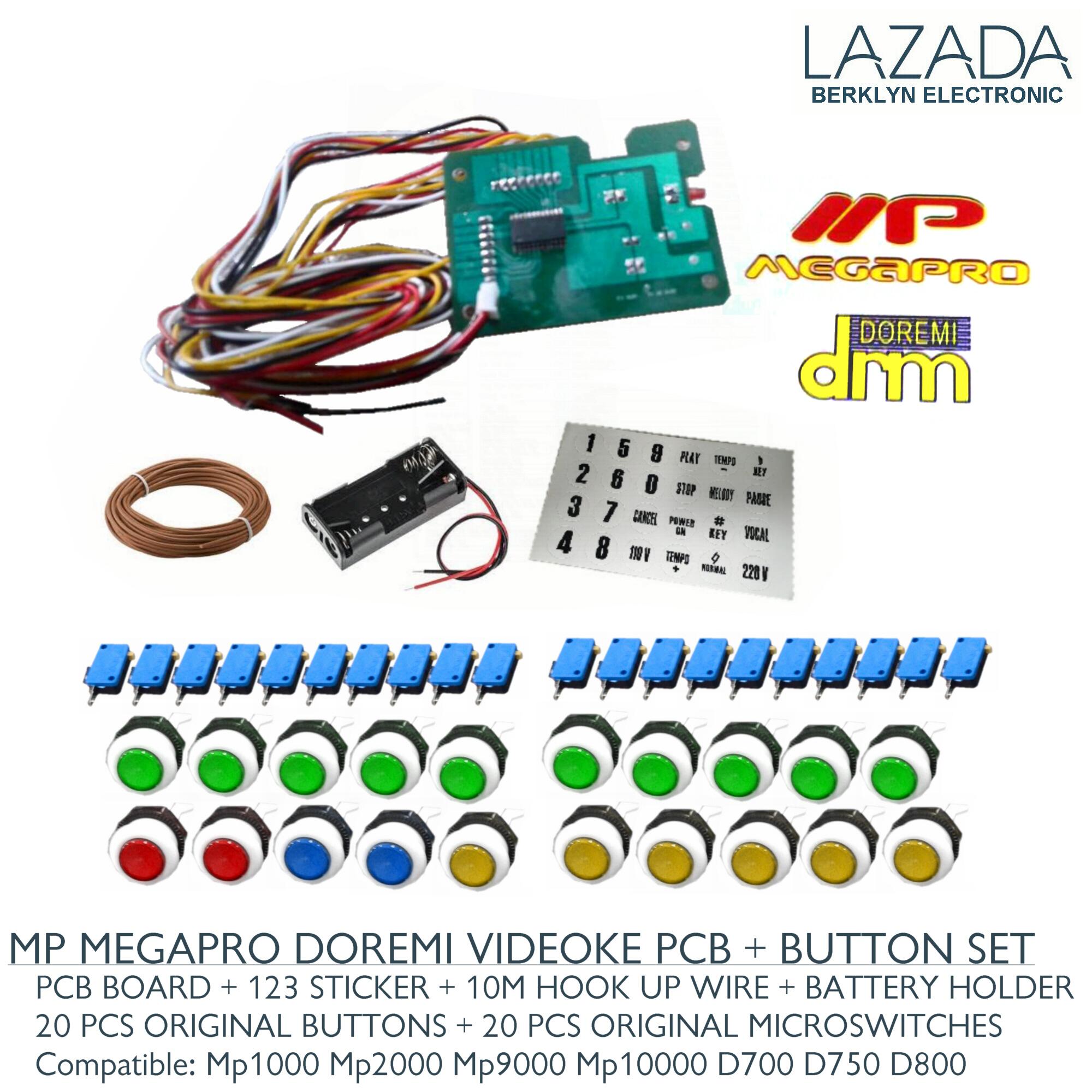
Videoke push button wiring diagram. You will be able to know precisely when the projects ought to be accomplished which makes it easier for you to properly manage. L the schematic or line diagram includes all the components of the control circuit and indicates their. This is a pretty straight forward wiring diagram outlining the electrical connections that need to be made in order to swap the ignition in a. Injunction of 2 wires is generally indicated by black dot on the junction of two lines. Push buttons shown in figure 1 are the most common type of control devices found in industrial facilities. Wiring diagram of 240sx keypadpush button start.
Therell be primary lines that are represented by l1 l2 l3 and so on. Push button switch wiring diagram perfect ignition relay wiring push button starter switch wiring diagram. Price player 6500push button and micro switch 25. Furthermore wiring diagram gives you enough time frame in which the assignments are to become finished. Almost all industrial machines contain push buttons even if the facilities operation is to set to run automatically. Stop ol m start 3 start start fiber optic transceiver class 9005 type ft fiber optic push button selector switch limit switch etc.
Popoy diy and more 32376 views. Typical push buttons are momentary meaning they are designed with a spring to keep the button contacts open or closed at all times. Fiber optic cable electrical connections boundary seal to be in. Ms megasound mega pro plus videoke keys wiring diagram ms 7000 jbns ms genesis mp 7000 jbns duration. But it does not imply link between the wires. As stated earlier the lines at a push button starter switch wiring diagram represents wires.
Ms megasound mp megapro plus dvd push button actual wiring diagram for videoke machine duration. Rating is available when the video has been rented. Popoy diy and more 22609 views. Wiring diagram book a1 15 b1 b2 16 18 b3 a2 b1 b3 15 supply voltage 16 18 l m h 2 levels b2 l1 f u 1 460 v f u 2 l2 l3 gnd h1 h3 h2 h4 f u 3. This feature is not available right now. Typical wiring diagrams for push button control stations 3 genera information at each circuit is illustrated with a control circuit continued schematic or line diagram and a control station wiring diagram.
At times the wires will cross.


