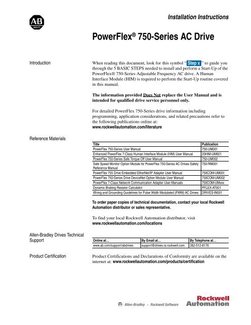
Drive powerflex 70 or powerflex 70 drive. Reference materials title publication powerflex 70 700 reference manual vol.

20ad011a3aynarc0
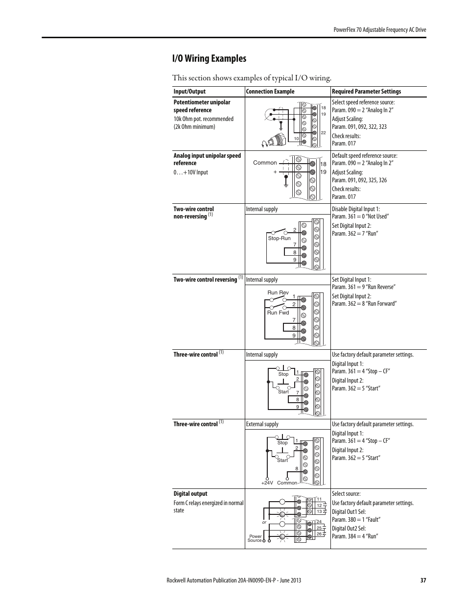
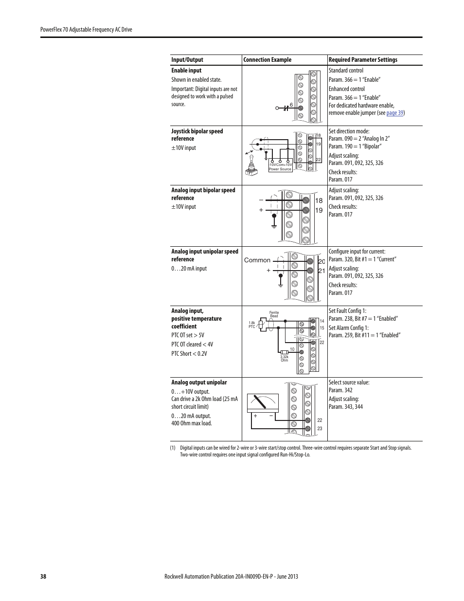
Powerflex 70 manual wiring diagram. For allen bradley drives technical support. Manual conventions in this manual we refer to the powerflex 70 adjustable frequency ac drive as. 1 18 installationwiring disconnecting movs and common mode capacitors powerflex 70 drives contain protective movs and common mode capacitors that are referenced to ground. Powerflex 70 drives are designed to worldwide standards providing out of the wiring and grounding guidelines for pulse width modulated pwm ac drives. Powerflex 70 wiring schematic the wiring diagram on the opposite hand is particularly beneficial to an outside electrician sometimes wiring diagram may also refer to the architectural wiring program the simplest approach to read a home wiring diagram is to begin at the source or the major power supply basically the home wiring diagram is simply utilized to reveal the diyer where the wires are. Powerflex 70 wiring schematic wiring diagram database.
Allen bradley powerflex 70 fault codes and descriptions. 1 pflex rm001 powerflex 70ec 700vc reference manual pflex rm004 driveguard safe off option series b for powerflex 40p and powerflex 70 ac drives 20a. Powerflex 70 ec and 700 vc reference manual publication pflex rm004 provides detailed drive information including operation parameter descriptions and programming. For detailed information on installing and wiring a safety relay system refer to the driveguard safe torque off option series b for powerflex 40p and powerflex 70 ac drives user manual publication pflex um003. The following manuals are recommended for general drive information. To help differentiate parameter names and liquid crystal display lcd text from other text the following conventions are used.
Parameter names appear in brackets. Wiring and grounding guidelines for pulse width modulated pwm ac drives publication drives in001. Check the motor and external wiring to the drive output terminals for a grounded. To prevent drive damage these devices should be disconnected if the drive is installed on an ungrounded distribution system where the line to ground voltages on any phase.


