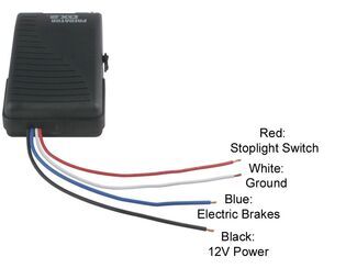
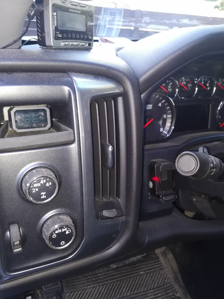
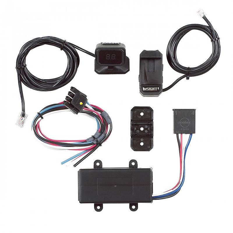
I could not find any order history based on your email address but for the hopkins insight trailer brake controller if you see power levels indicated when you press the manual override lever there should be output on the blue wire that gets routed to your 7 way trailer connector. We offer universal installation brake controls as well as vehicle specific electronic controllers.

Installation Of A Hopkins Insight Brake Control
Insight brake controller wiring diagram. Auxiliary connection is optional it may be connected to any 12v to 24v constant power source or left unconnected. Trailer parts tech tip. Electric brake controller wiring diagram. Typical vehicle brake control wiring diagram. Elecbrakes is designed to operate 1 to 2 braked axles. This brake control is not reverse polarity protected.
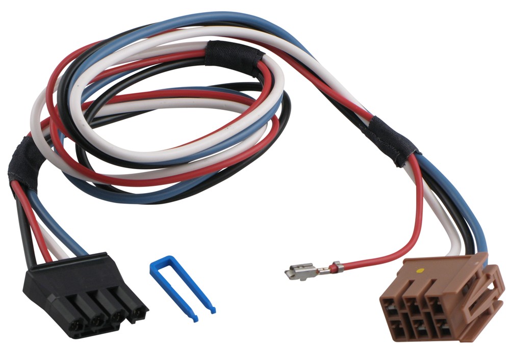
Installing a brake controller involves disconnecting the vehicle battery mounting the brake controller onto dash and plugging the unit in with a vehicle specific wiring harness. Break away systems may be added to the service brake circuit. If your vehicle is not equipped with a plug and play harness you can also splice in wiring for connecting a brake controller. In this event the manual brake must be depressed to actuate the brakes. From the time based output models to the inertia mechanical motion sensor units these electric trailer brake controllers are among the best systems available. Moving the brake control will not automatically apply the trailer brakes.
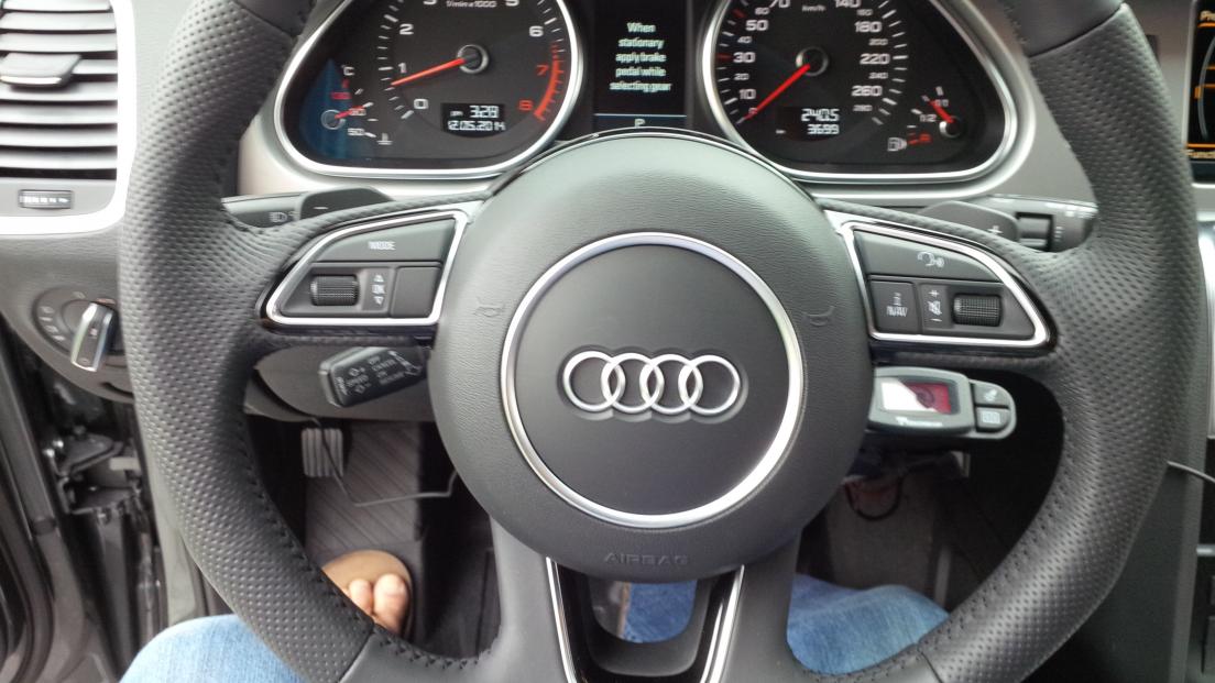
In this guide we cover step by step how to install a brake controller. The insight controller is much safer because it has a readout on my windshield a manual control beside my steering wheel and the power box is far enough under my dash that i never have to worry about banging my knees on it. Reversing the connection to the vehicle battery or the breakaway battery on the trailer will damage the brake control.
