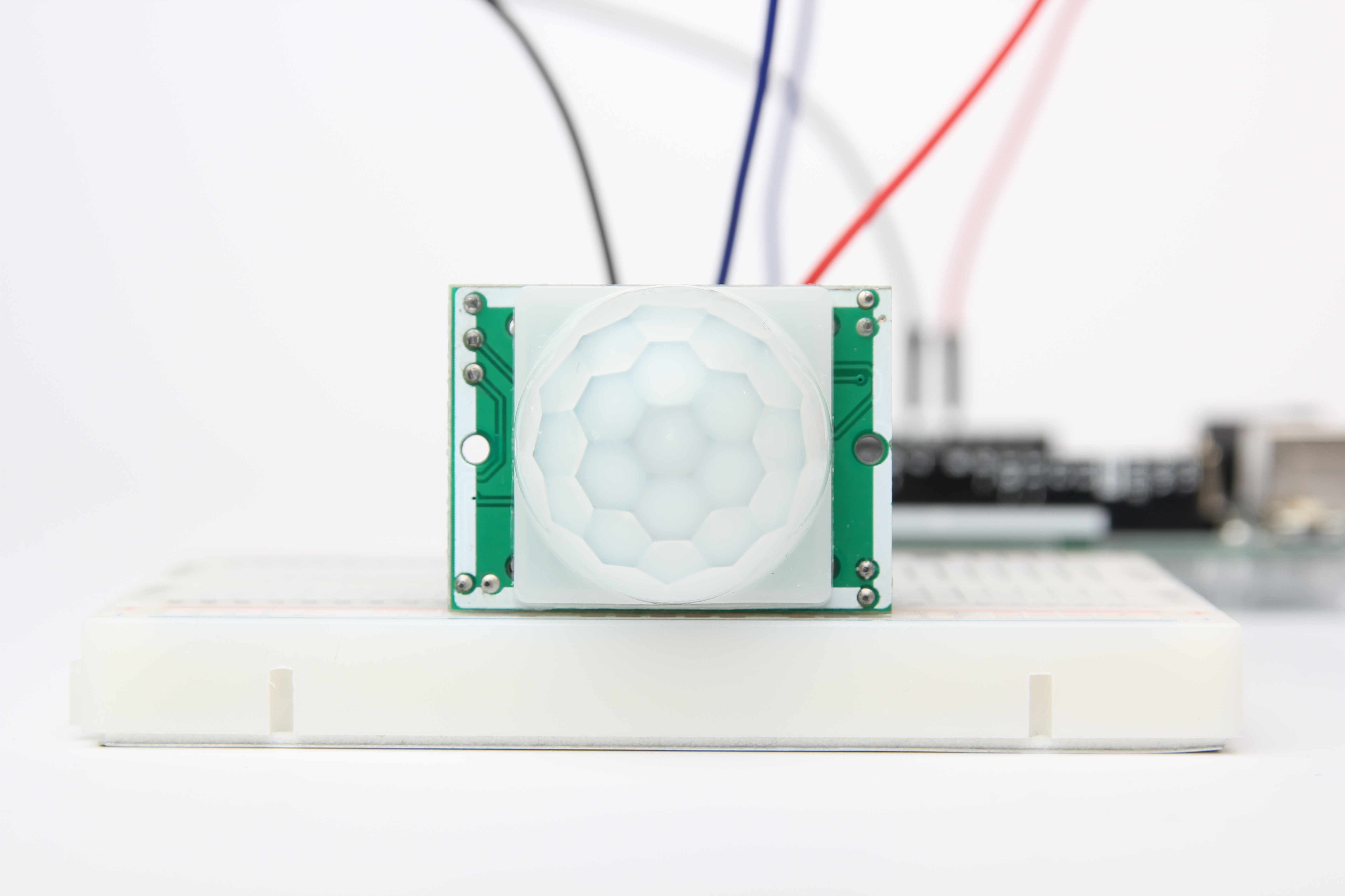
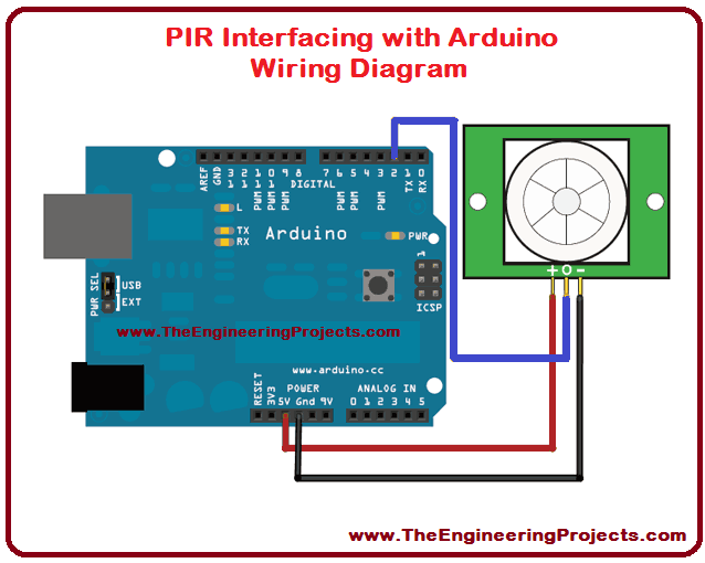
The passive infrared sensor consists of three pins as shown below. A wiring diagram is a simplified conventional pictorial depiction of an electrical circuit.

Multiple Motion Sensors In One Room Faradite
Pir motion sensor wiring diagram. Pin1 pin2 and pin3 are corresponded to drain source and ground terminal of the device. More electrical tips and diagrams wwwaboutelectricitycouk like. It consists of guidelines and diagrams for various kinds of wiring techniques along with other items like lights home windows etc. Lighting circuits connecting a pir motion sensor with an override switch. It reveals the elements of the circuit as streamlined shapes and also the power and also signal connections between the tools. Variety of motion sensor light wiring diagram.
Diy pir infrared motion sensor switch smart security led light motion sensor wiring diagram wiring diagram consists of numerous in depth illustrations that display the relationship of varied things. Go through the given diagram of the pir sensor to understand its pin outs and arrangement in the circuit. In this video you will see how to wire pir sensor light in the ukit will also show you internal wiring of pir sensor and light. Wiring for lights that can either be off operated by a motion sensor or permanently on. Pin 1 is vcc which is connected positive 5v supply. The cable marked supply is connected to the consumer unit or some other source of power such as a fused connection unit or plug.


_nwG9NMO2At.png)