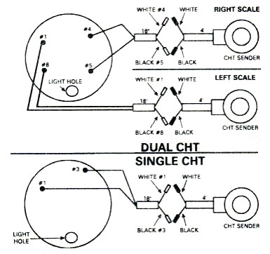
Refer to the wiring diagram diagram g. Vdo mounting bracket and nuts 1 5.
Boost Gauge Drawing Chilangomadrid Com
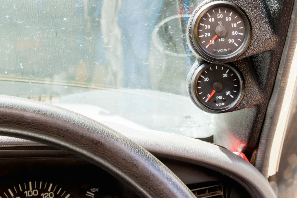
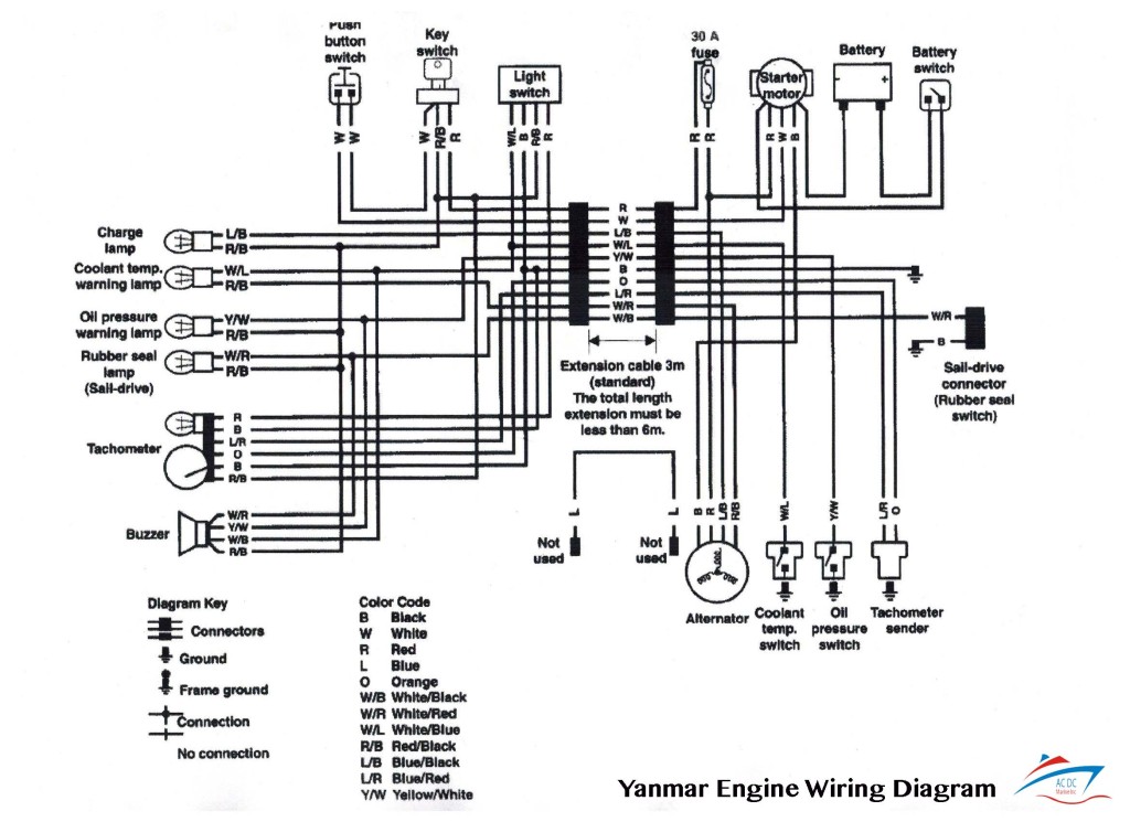
Vdo egt gauge wiring diagram. Always disconnect battery ground before making any electrical connections. Connect the shield and ground wire to the ground post on the msd box or the main msd ground. Wire gauges in series from a positive accessory to a source which is not already overloaded with fans air conditioning and such. Light bulb 12 volt ge. Read these instructions thoroughly before making installation. Note use 18 awg for wire harness read these instructions thoroughly before installation.
Vdo gauge cockpit vision this special kit includes the full pyrometer kit 310159 plus a boost gauge of your choice line kit package deal save save save. Repair service for aftermarket gauges and accessories connie heflin phone. Vdo spin lok clamp or mounting bracket 1 5. Read these instructions thoroughly before making installation. Installation instructions 1 caution. Aftermarket technical support troubleshooting.
Do not deviate from assembly or. 158 or equivalent 1 4. Follow this wire to a junction and attach the wire from pin 4 at this junction ie. Vdo gauge cockpit vision pyroegt. Please be certain to follow the instructions for your specific gauge. If you have additional questions please contact vdo.
The ground œ wire is also run in series including the light socket ground. Connect the power wire to the ignition terminal on the msd box and the signal wire to the tach output terminal on the msd box. Installation instructions 1 caution. The final ground run using 14 gauge wire should be connected to a good. Singleviu 52mm 1000c exhaust gas temperature gauge. Do not deviate from assembly or wiring instructions.
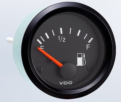
Always disconnect battery ground before making any electrical connections. Connect the wire from pin 4 to a switched 12 volt or 24 volt source. A switched 12 or 24 volt wire can be found coming from the ignition switch. Temperature pressure or fuel gauge 2⁵₈ 66 mm diameter 1 2. Temperature gauge pressure gauge rudder angel gauge trim gauge fuel gauge fresh water gauge for level type sensor tu00 0752 5207102 1 6 3 technische änderungen vorbehalten technical details subject to change tu00 0752 5207102 gb if the instrument is mounted flush ie from the back so that the instrument glass and the panel form one. Thermocouple connection is by 14 inch 18 nptf compression fitting.
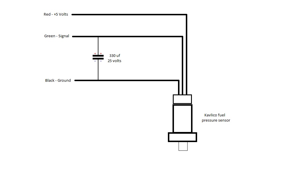
Connect a wire from pin 5 to a constant 12 or 24 volt source. Mounting dimensions vary for different gauges. Retail pack with harness add to compare. At the tach end connect the red wire to power the green wire to signal and the black wire to ground see diagram i on page 5. Refer to diagram d. Suitable for most exhaust systems.
1 800 265 1818 do not cut sender wire. Repair service for oem instrument clusters and systems merri mcintyre phone. Do not deviate from assembly or wiring diagram. Lamp socket push in wedge type 1 3.

