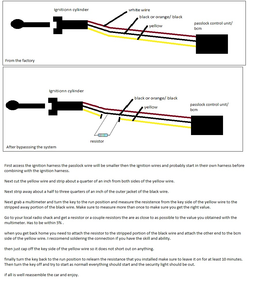
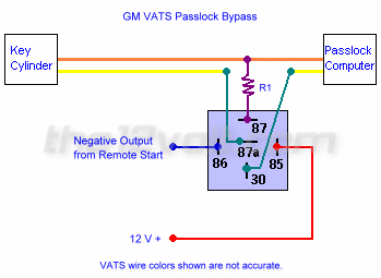
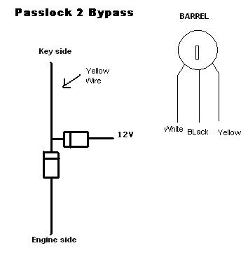
Vats and passlock i ii data bypass kit for buick cadillac chevrolet gmc hummer isuzu oldsmobile pontiac and saturn vehicles. Passlock 2 wire diagram for 8 pin harness on if 114 bypass module.

Vats Passlock Transponder Universal Alarm Bypass Module
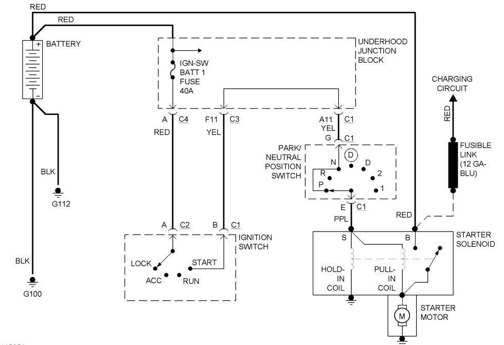
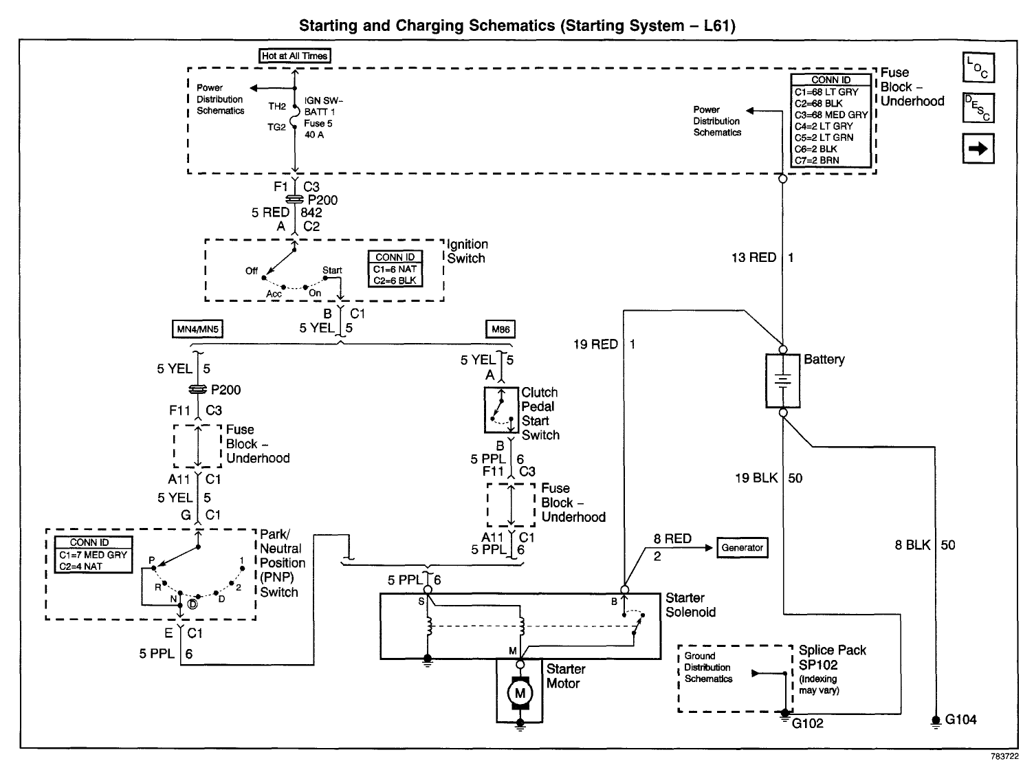
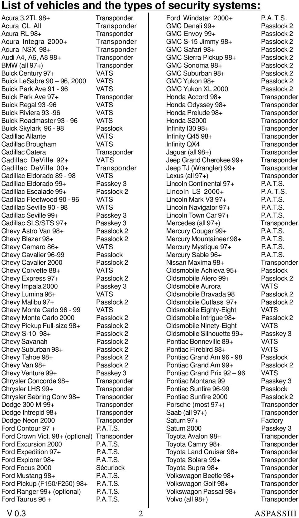
Passlock 2 wiring diagram. This is a diagram for passlock 2 when connecting the if bypass module when using this diagram the wires marked in. Click here to see a typical passlock wiring diagram. We found it from reliable resource. Chart below will tell you by vehicle which wiring diagram to use. Self learning no additional programming required. Listed below are a number of top notch gm passlock wiring diagram photos on internet.
If you have a passkey system click here to see the reset procedure. Locate two wires which are thin and are in the main ignition harness. Start the vehicle and keep it running for at least 10 seconds. To determine which system you have follow these instructions. Passlock sl2 v2 general motors passlock data bypass kit. Gm pass key iii plus bypass for vehicles equipped with the new style hybrid passlock.
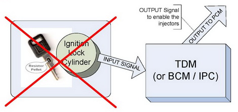
The vehicle must be started within 15 seconds or the module will automatically exit the learn routine. Reset security system on chevy buick oldsmobile cadillac pontiac saturn hummer. Passlock 2 wires key side of passlock 2 wires o yellowred to key side of. That saves a lot of time because you dont have to refer back to the component locator or circuit locations. How to override bypass a gm passlock 1 2 vats factory anti theft system passkey in gm cars there is a bundle of three wires which go from the body control module to the ignition switch. Acquire the same size resistor and 3 relays and perform the connections shown in the diagram below.
The gm passlock system is a key based fuel shutdown anti theft system passlock i wiring diagram this wire is located in the vehicles three wire passlock. Cycle the ignition onoff 2 times. Passlock 2 wire diagram for 8 pin harness on if bypass module. Harness 2 passlock ii wiring diagram the module must first be programmed before operation use the following procedure. Passlock ii bypass procedure there are 2 types of passlock ii systems. This is a diagram for passlock 2 when connecting the if 114 bypass module when using this diagram the wires marked in red are used for passlock 2 all other wires tape up and do not use.
Click here to see the trouble codes for a passlock system.

