Kohler rxt transfer switch install free download as pdf file pdf text file txt or read online for free. Rxt ats 200 amp service entrance.

Packages
Kohler rxt transfer switch wiring diagram. Date poles wires amps hertz bar code phase volts serial no. Connect the utility. 0kb specification sheet 0kb wiring diagram 0kb accessories. D use kohlers. It shows the way the electrical wires are interconnected which enable it to also show where fixtures and components could be. Statusload management indicator rxt.
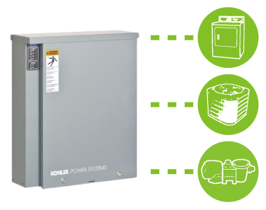
With an rxt transfer switch 200 amp. Starting at 4900 msrp see the status of your rxt automatic transfer switch at a glance. All single phase kohler generators with rdc2 or dc2 controllers. A wiring diagram is a simple visual representation of the physical connections and physical layout associated with an electrical system or circuit. How to make a 12 kw generator power a 200 amp service. The led indicator lets you know whether power is coming from the utility.
Section 4 service disconnect se model. Starting at 3200 msrp see the status of your rxt automatic transfer switch at a glance. Kohler transfer switch wiring diagram what is a wiring diagram. Schematic diagram 0kb specification sheet 0kb wiring diagram 0kb accessories. The led indicator lets you know whether power is coming from the. With a load shed kit and added relay modules.
See the transfer switch operation and installation the engine start and load transfer time delays prevent manual for connection instructions. 0kb specification sheet 0kb wiring diagram 0kb accessories. For emergency systems listed r figure 3 typical transfer switch nameplate model rxt. Transfer switch gm21291 e 1 2 3 1. The connection points on the transfer switch contactor are labelled normal emergency and load. The load must be connected to the load control output to a kohlerr model rxt transfer switch.
On the interface board of the model rxt transfer switch. All kohler generators with rdc2 or dc2 controllers. Refer to the transfer switch dimension drawings and wiring diagrams for planning and installation. G11 140 model rxt automatic transfer switch 320g page 3 optional combined interfaceload management board the rxt transfer switch is available with either a standard interface board or a combined interfaceload management. Refer to the connection diagrams on the transfer switch enclosure door and the wiring diagrams in section 6. Factory installed accessory numbers material for emergency systems transfer switch type enclosure mfg.
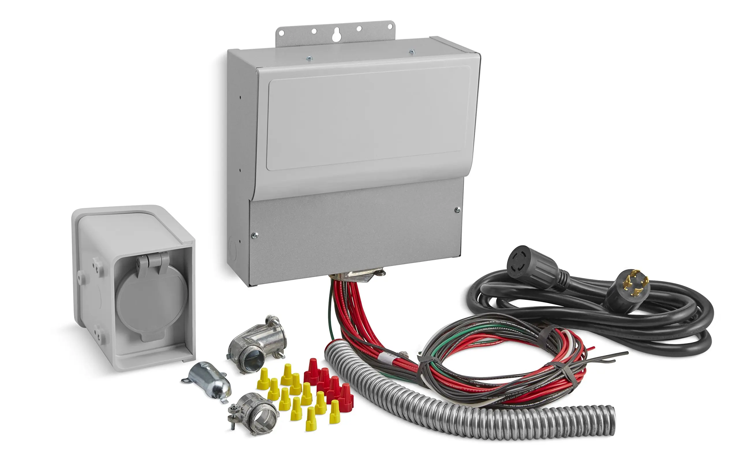
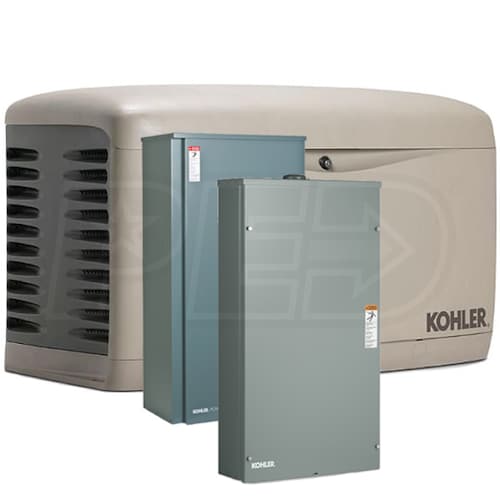
Comes with either an rxt 100 amp indoor rated automatic transfer switch with 16 circuit load center or rxt 200 amp outdoor rated service entrance rated automatic transfer switch with load shed kit quiet neighborhood friendly operation with sound levels similar to a typical central air conditioner.


.png)


