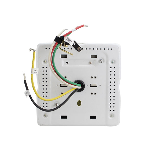
Class 1 0 10v and power wires configuration button class 2 0 10v wiring terminal ports cable tie ring lmrc 112 line voltage class 1 0 10 volt control wiring scene switch. The lmrc 211 347 is rated for up to 15a.

Specialty Controllers Switches Alpscontrols Com
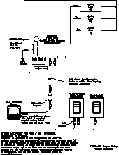
Lmrc 111 wiring diagram. Do not connect different load types to the relay. All line voltage wiring is 16 awg. 90 111 lmrc 101 one relay wiring diagram dxf 26766kb 90 932 restroom w switch and fan control dxf 356mb 90 932 restroom w switch and fan control. Lmrc 111 1 relay room controller 0 10v dimming 120277vac 10a ballast. Terminate wiring according to wiring diagram. Lmrc 212 and the lmrc 212 347 room controllers each have two load relays.
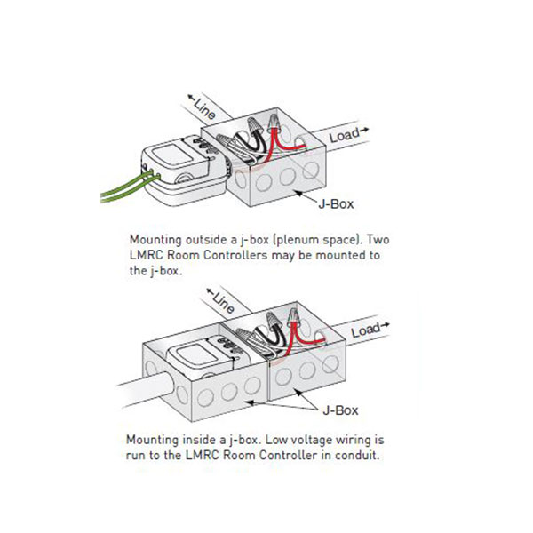
Network ports not shown. In a dlm local network with only lmrc 212 or lmrc 212 347 room controllers the room controller with the highest serial number is the master carrying load 1 and load 2. Lmrc 111 lmrc 111 m lmrc 112 lmrc 112 m mounting wiring and connecting to a dlm network the lmrc 111112 room controller can be mounted external to any junction box with 12 knockouts placing it in the plenum space. Wattstopper digital 1 relay room controller has voltage rating of 120277 volt ac at 5060 hz. All line voltage wiring is 12 awg. Lmrc 221 75 c copper wire only santa clara ca 8008798585 industrial control equipment 46a9 indoor use only mounting the controller the room controller mounts to a four square deep junction box using the included mounting plate with the hinge pins extending away from the box as shown.
Each relay is rated for up to 20a. For dimming ballasts or drivers connect the 0 10v control wires to the 0 10v terminals that match the load relay output connection. Lmrc 110 series room controllers include one or two relays to switch a total of 10 amps a high efficiency switching power supply and dual 0 10 volt outputs per relay for control of dimmable loads including compatible led drivers or electronic ballasts. The lmrc 213 communicates to all other dlm devices connected to the dlm local network. Lmrc 210 series digital room controllers include one two or three relays to switch a total of 20 amps a high efficiency switching power supply and one 0 10 volt output per relay for control of dimmable loads including electronic ballasts. The lmrc 211 is rated for up to 20a.
It has plug n go automatic configuration for easy installation and maximum energy efficiency. Total load for lmrc 112 not to exceed 10a. Sample connection diagram with class 1 class 2 dimming control wiring. Connections shown are for example only. It measures 44 inch x 32 inch. All line voltage wiring is 12 awg.
The next highest serial number would have load 3 and load 4 and so forth. Each relay is rated for up to 10a. Total load for lmrc 213 not to exceed 20a. The low voltage lmrj cables can connect to any dlm device with an open rj45 receptacle.


