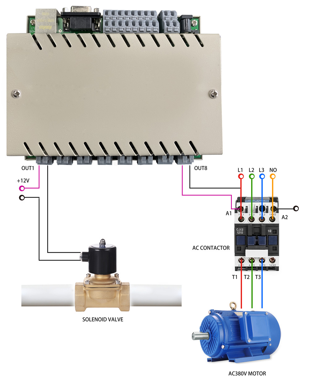
Sprinkler wire is available with varying numbers of color coded wires inside of a larger plastic sheathing. You will need multi strand wire with enough wires for each valve plus one more to connect the valves to the timer.
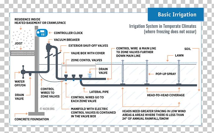
Wiring Diagram Circuit Diagram Electrical Wires Amp Cable Png
Irrigation valve wiring diagram. 7 core irrigation cable. From the valves run pipe through trenches to the sprinkler heads. This is a basic pump start wiring diagram for most controllers. The usual components in a wiring diagram are ground power supply cable and also link result devices switches resistors logic gate lights etc. The wire for this particular valve box started at the valves snaked its way through a rock retaining wall and under a deck filled with creep crawlies and then under a rock walkway before being buried in a few inches of dirt and entering the. Please select your valve from the list below.
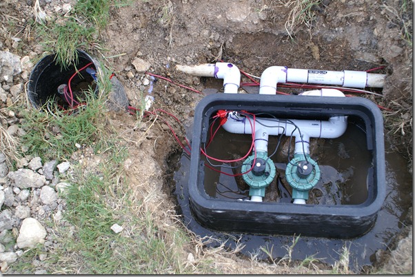
All these valves were in one sprinkler box and i could soon tell the problem was with the wiring. Wiring sprinkler control valves. 13 core irrigation cable. It shows the components of the circuit as simplified shapes and the gift and signal links between the devices. Irrigation controller wiring diagram wiring diagram is a simplified adequate pictorial representation of an electrical circuit. This article explains how to wire an irrigation valve to an irrigation controller.
5 core irrigation cable. 9 core irrigation cable. One colored wire is needed for each sprinkler valve in the system plus a white common. The following diagrams show wiring details for pump start relay and pump motor starter wiring for various rain bird controllers. This diagram assumes the master valve circuit is being utilized for the pump start circuit. Tips on installation and maintenance of residential irrigation valves.
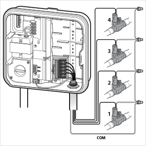
To read a wiring diagram initially you have to understand just what fundamental elements are included in a wiring diagram and also which pictorial signs are utilized to represent them. You will need one individual wire for each solenoid valve and one common wire to be shared by all the solenoid valves. Instruction manuals brochures and troubleshooting guides for rain bird products have been formatted in adobe acrobat pdf for easy downloading and printing. You may have noticed a trend you will always require at least one extra wire. Use low voltage insulated cable approved for burial usually awg 14 or 18 to connect the timer to the control valves.






/lawn-water-sprinkler-164650339-f6ba31b39f114800b15c13c5b21f7856.jpg)

