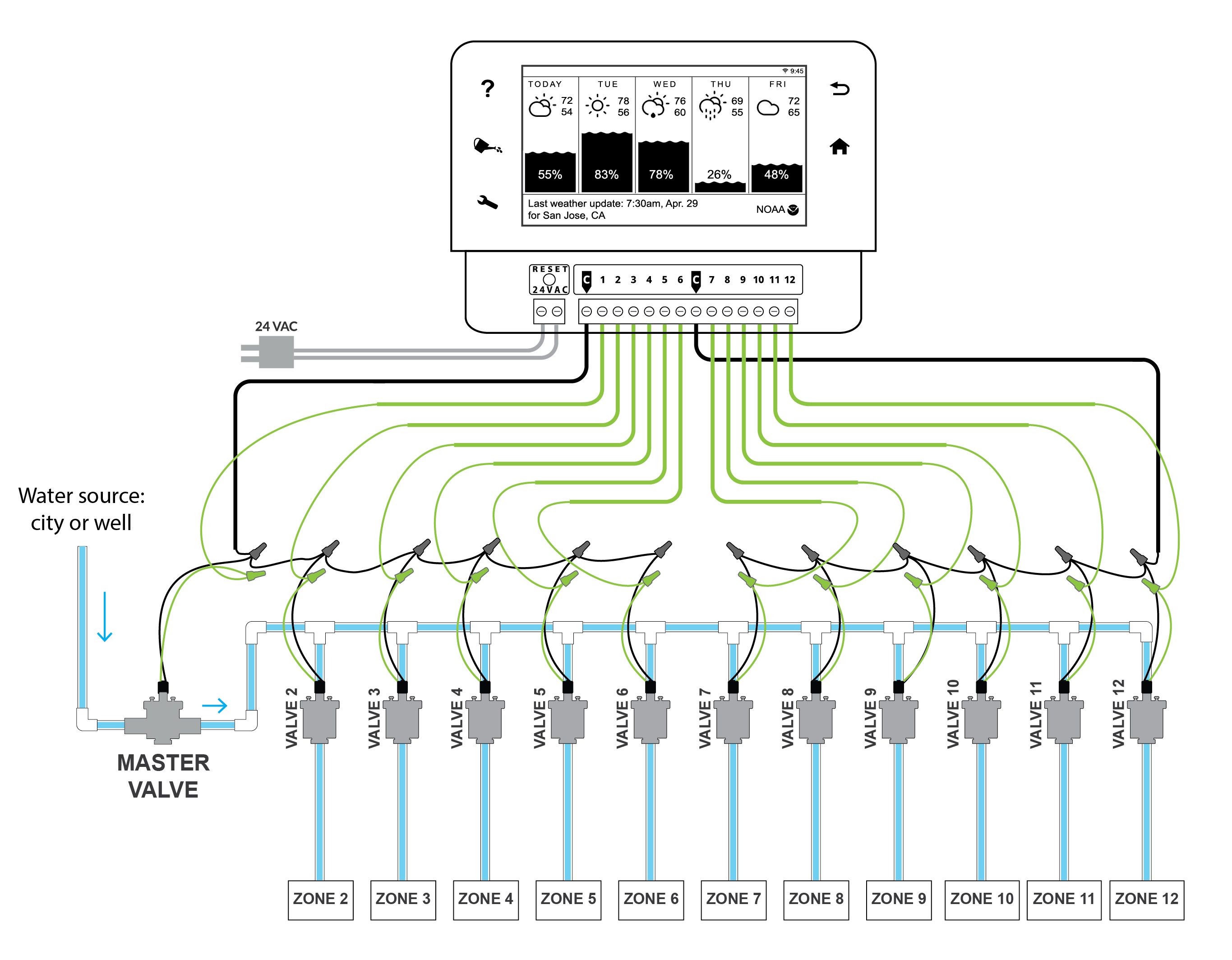
Sprinkler wire is a vital part of an underground system. This article explains how to wire an irrigation valve to an irrigation controller.

How To Wire Your Controller Basic And Advanced Wiring
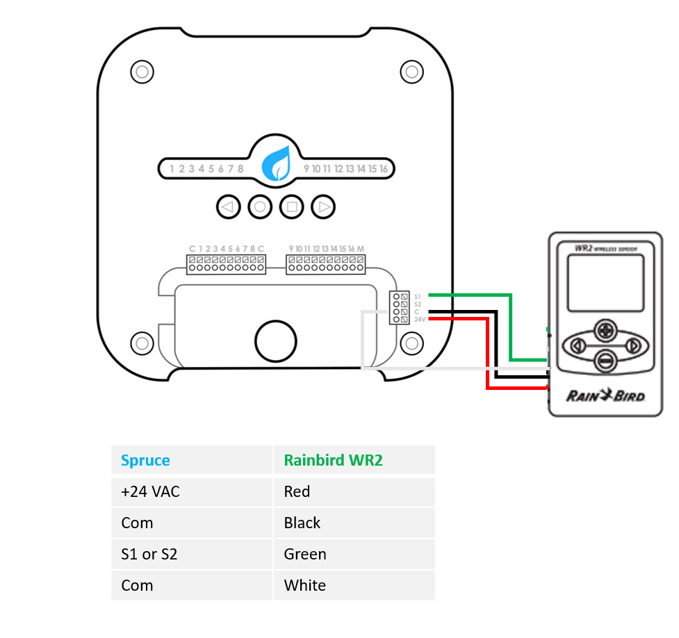
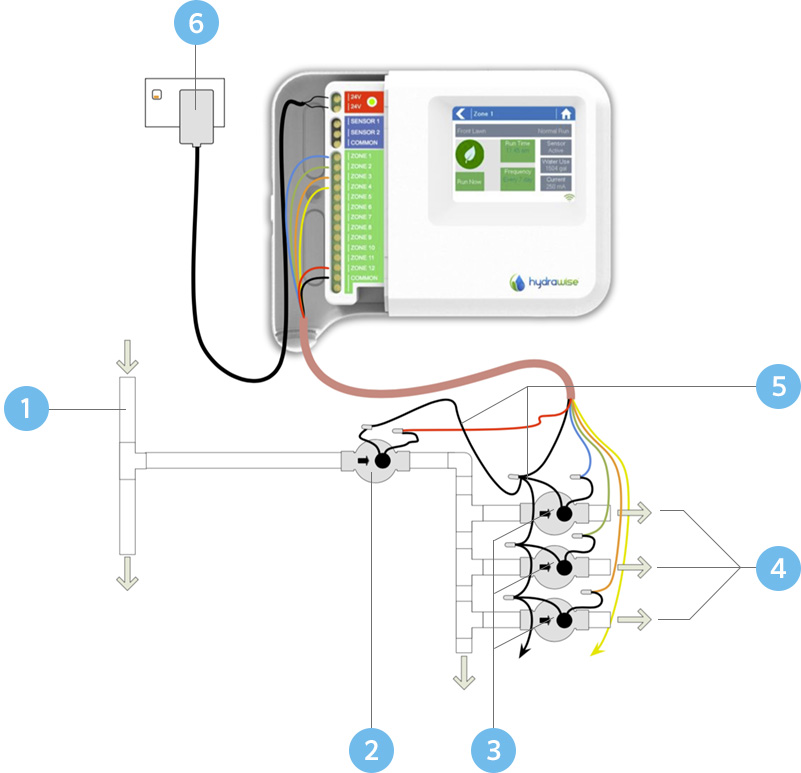
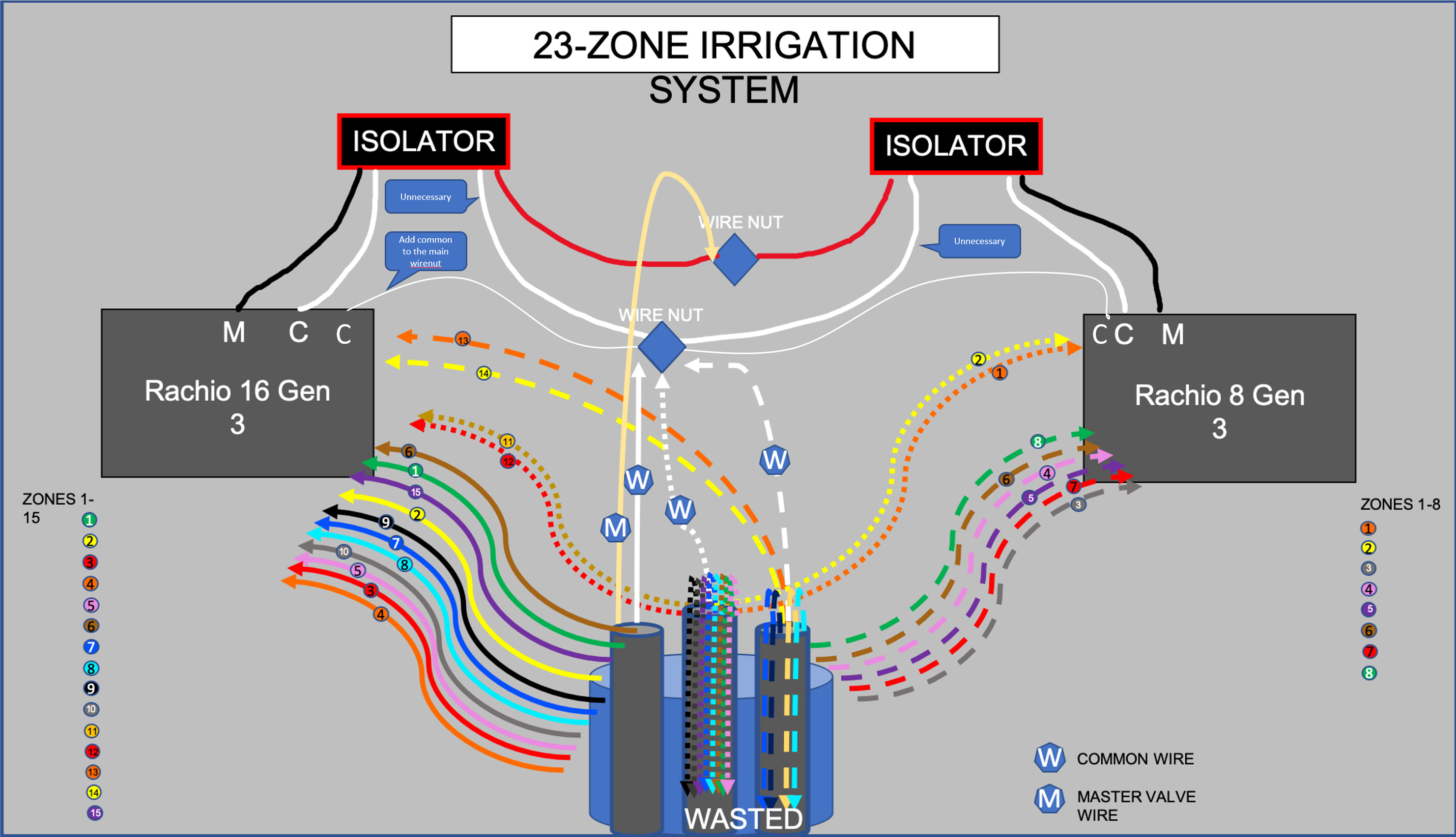
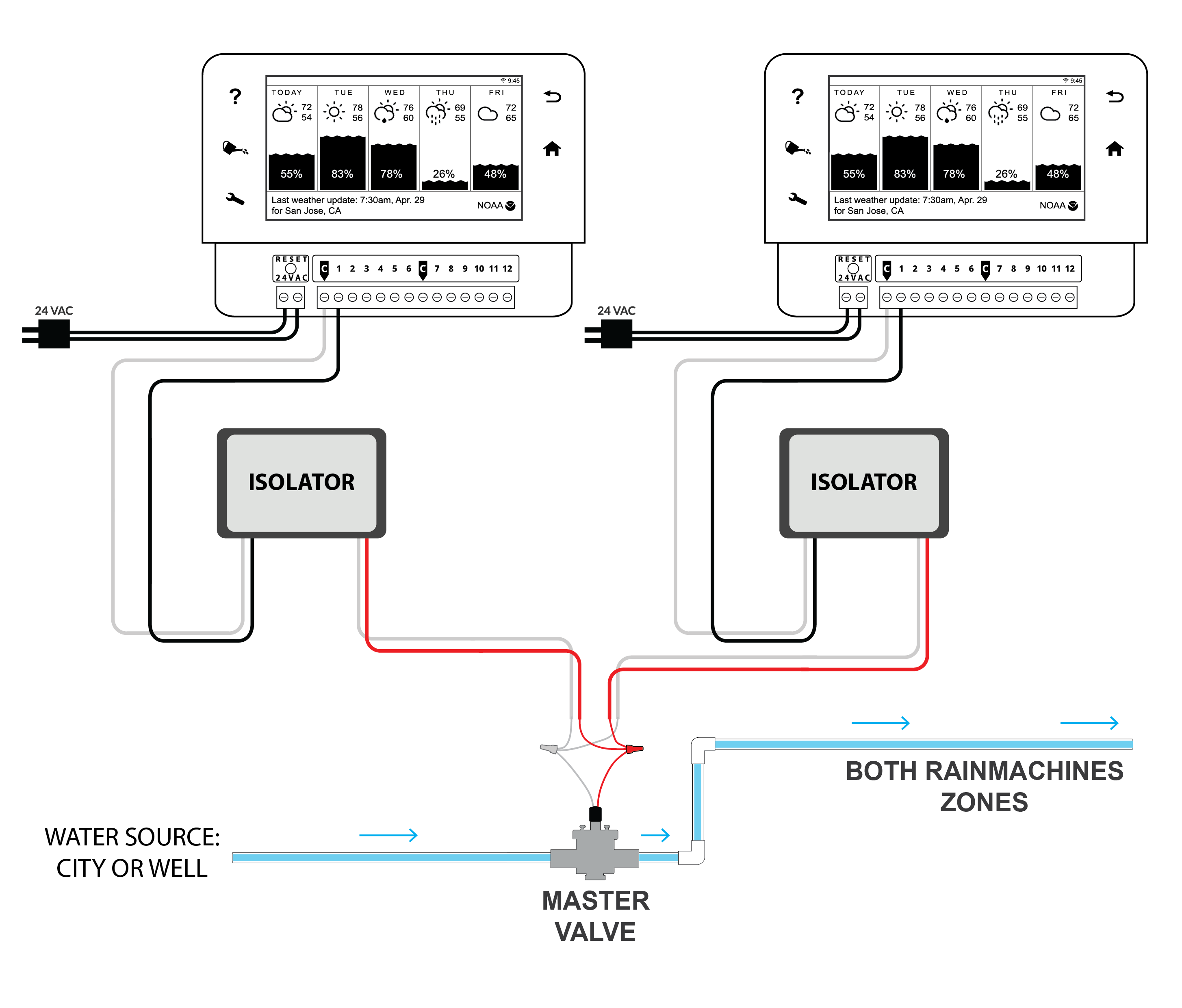
Irrigation controller wiring diagram. In general the. The usual components in a wiring diagram are ground power supply cable and also link result devices switches resistors logic gate lights etc. If your system is a little more complicated you may have more wires than zones to accommodate things like master valves pump start relays and indexing valves. Wiring a sprinkler system controller is fairly straightforward and involves matching your systems wires to the correct terminals. In those that do the wire colors reflect the station number the wire controls. Rain bird offers many types of sprinkler systems and they dont all come with color coded wires.
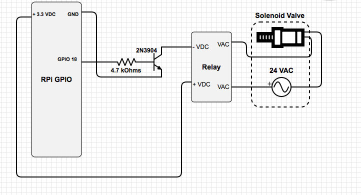
If more than one controller is in operation at the same time controller a takes precedence over controllers b c and d. To read a wiring diagram initially you have to understand just what fundamental elements are included in a wiring diagram and also which pictorial signs are utilized to represent them. Controller c will take prece. Controller b will take precedence over c and d. And because timers and valves are often separated by some distance it can be a bit pain to repair. This wiring diagram shows us the wiring for four controllers wired to one pump starter and one common wire for all valves on all four controllers.
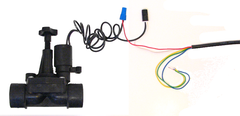
If it breaks the system wont work negating all the benefits of having it in the first place. Use color coded irrigation wire to connect the valves to the controller. It shows the components of the circuit as simplified shapes and the gift and signal links between the devices. The total number of wires you need is one for each of the electric valves plus one common wire. If you are wiring a 5 zone system purchase a combination of wires with at least 6 total wires long enough to reach from your controller to the farthest valve. Irrigation controller wiring diagram wiring diagram is a simplified adequate pictorial representation of an electrical circuit.
