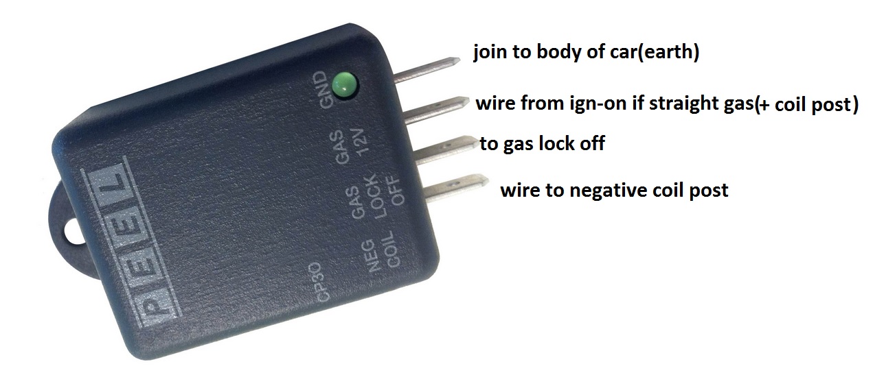
Bluyel lpg swtch 12v pin 12. I bought myself a peel cp94 box for my dual fuel xf.

Peel Lpg System Round 7 Led Dash Gauge And Switch Cp309gs
Peel lpg wiring diagram. Diagrams for the following systems are included. Ive rewired lights ign etc but not sure about the gas side of things. Lpg wiring diagram pdf wiring diagram is a simplified conventional pictorial representation of an electrical circuit. 100 of gas in the tank green 7 onoff button changes the tech controller working mode. Small engine closed loop lpg propane emission controls. Red batt 12v rear view pin 10.
This video demonstrates the ford falcons complete wiring diagrams and details of the wiring harness or connectors. Purple fuel pump relay power side pin 7. Radio wiring engine wiring. 25 of gas in the tank green 4 app. Found it odd it had a switch to engagedisengage the cut off to the tanks. I followed the wiring diagram found online to run with the gas going to the positive terminal on the gas gauge inside the tank 12v teeing into the gas solenoid valve as that was the only wire in my boot that had 12v and i already tried using the positive on the petrol sender but that.
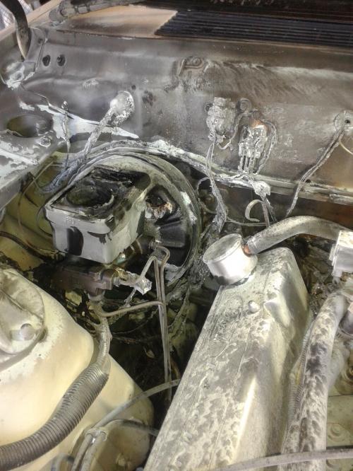
Im having some troubles getting it to work at all. Had a look under the bonnet and hes poorly wired in a switch from the 12v cutoff solenoid the one on top of the converter to the loom essentially bypassing it manually when i startstop the car. In the lpg mode and the amount of petrol when operating on petrol fig. I had a fire under the bonnet a while back witch took out most of my wiring. 50 of gas in the tank green 5 app. With a high amount of development time and engineering peel electronics designed and manufactures a full closed loop system for small engines for the reduction of co levels hydrocarbons co2 and nox also fuel reductioneconomy of up to 30 40.
Prins vsi 1 and vsi 2 installation manual diagrams. But any info would be appreciated. 75 of gas in the tank green 6 app. Brown to fuel pump side pin 6. Led switchboard chart 1 gas on indicator blue 2 gas reserves indicator red 3 app. In the lpg mode the 12 volt signal wire to the pcm is removed and 12 volts is applied to the lpg mixture control computer and the lpg valves via an electronic safety cut out.
Pink tacho input pin 5. Redblack lpg sender pin 14. Hi guys bought a factory lpg falcon au ute a week ago. Black engine ground pin 15. It shows the components of the circuit as simplified shapes and the faculty and signal contacts in the middle of the devices. Whiteblue tps pin 1.
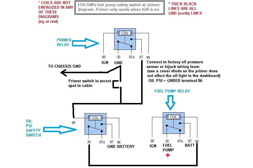
Ideally a diagram of the wiring connecting the coil cutoff valve primer peel cp30 etc. Green lpg lock off pin 2. Cheers peter edited may 25 2017 by xftoxe error. Tech lpg controller installation manual and controller programming manual figure 1. Wiring diagram pin 8. This enables the vehicle pcm to operate the lpg system and provides power to the lpg.


