Wire color gps 17n17hvs antenna black ground. A nmea 2000 power cable terminators an additional dropbackbone cable and additional t connectors are not included with a gfs 10 fuel sensor.

8735 96 97 98 Mustang Altenator Starting And Charging System
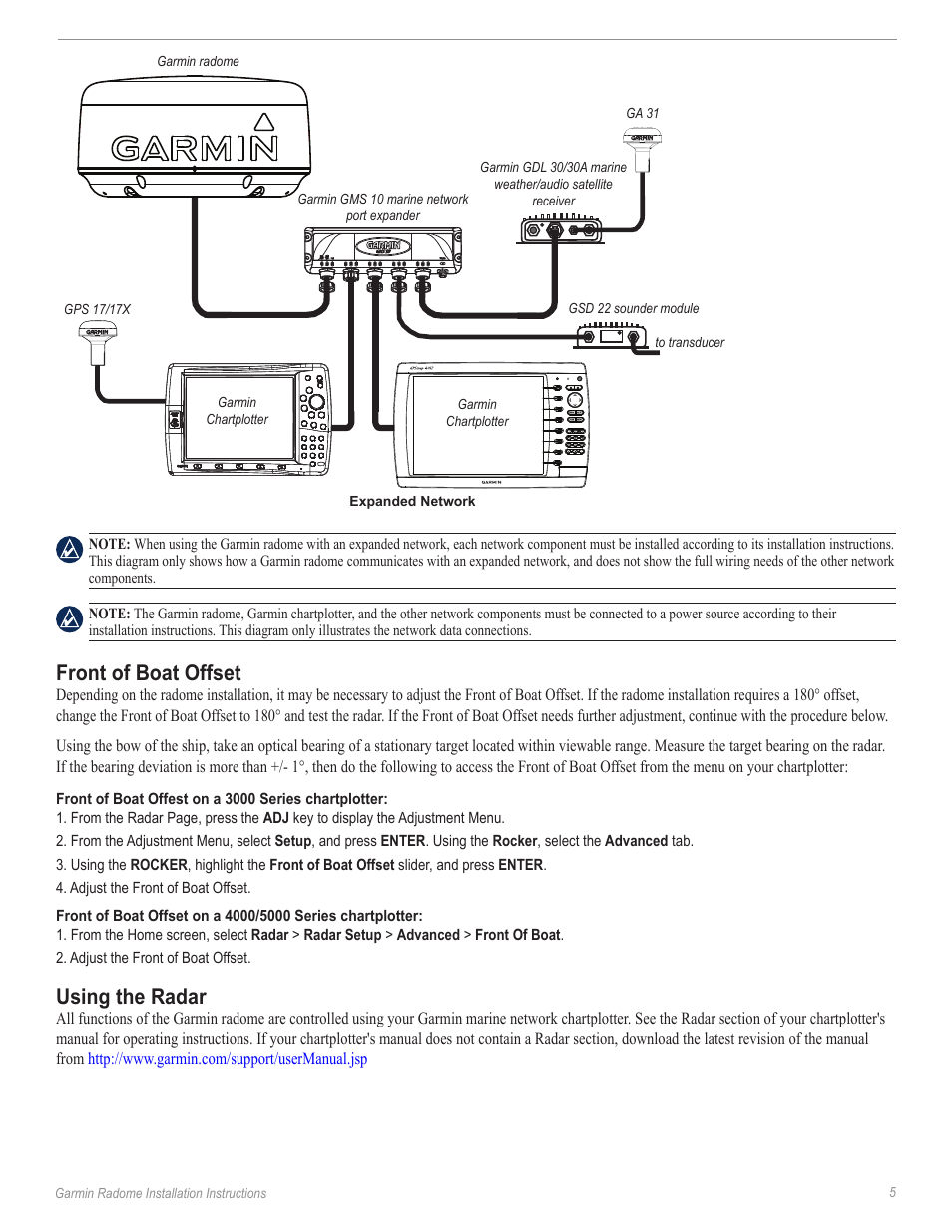
Garmin gms 10 wiring diagram. The gmi 10 is packaged with the necessary nmea 2000 connectors and cable to either connect the gmi 10 to your existing nmea 2000 network or build a basic nmea 2000 network. Rv navigator with a large edge to edge 8 display preloaded campgrounds and custom routing for the size and weight of your rv or towable trailer. With this robust 100 mb switch you can connect multiple multi functional displays mfds and sensors to the marine network and gain the benefit of ethernet like data transfer speeds up to 10 times faster than some competitive systems. Use 22 awg 18 awg for the red and black wires shielded twisted pair wiring for extended runs of wire. Page 2 connecting the 7 pin power cable to your boats battery or fuse block the gms 10 network port expander is designed to pass control signals to turn sensors such as the garmin marine weatheraudio satellite receiver on and off. The gms 10 network port expander allows you to connect multiple chartplotters and sensors over the garmin marine network.
T connector is included with a garmin gfs 10 fuel sensor. The gfs 10 fuel sensor as shown by the shaded components in the box diagram is intended to be connected to an existing nmea 2000 network on. You should create a service loop at least 25 cm 10 in long in the cables with the rotating joint centered on the loop. With this robust 100 mb switch you can connect multiple multi functional displays mfds and sensors to the marine network and gain the benefit of ethernet like data transfer speeds up to 10 times faster than some competitive systems. The gmb 10 network port expander allows you to connect multiple chartplotters and sensors over the garmin marine network. Thus when you power onoff a chartplotter that is connected to an expander all sensors that are also con.
Network cable to the expander. In this episode i unbox a garmin panoptix livescope and walk you through the install process in my ranger mpv 1652. Follow the directions and reference the diagrams on page 5. Contents gms 10 network port expander 010 00351 00 garmin marine network cable 320 00227 00 7 pin power cable 320 00023 05. Solder all connections and seal the connection with heat shrink tubing. Marine brochures garmin.
Then your garmin marine network devices will be able to share information such as weather mapping and sounder data as well as position information. I also show a diagram of all the connections you need to make to complete the. Powerdata cable wiring use the following diagram to connect the gps 17n17hvs antenna to a gpsmap 3000 series chartplotter. You should use the included tool a flathead screwdriver or a blunt knife to separate the cables.


