It is a system where digital commands are sent to the locomotives through the rails. Even if you arent technical you can see which ways are highly reliable and also dcc safe whether you are using dcc or dc now or perhaps going to dcc in the future.

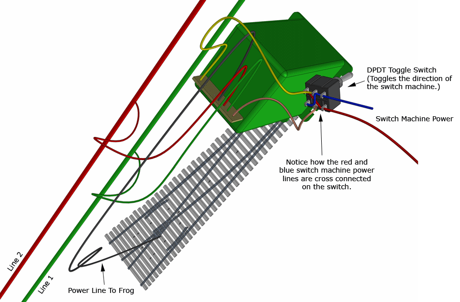
How To Wire Power Routing Model Train Turnouts
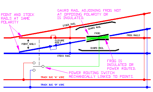
Basic dcc wiring diagram. Dcc advice 11 page 3 wiring point work special track conditions for dc or dcc wiring and switching frogs lets get the basics sorted out first. 10 gauge 14 gauge solid conduit wire 14 gauge more than sufficient for 100 feet run in ho 3 feet ok between feeds closer on smaller code track. Basically the home wiring diagram is simply. Note how all the connections are either red or black and therefore can be joined into a total of two wires see the two wire myth in part 1 on dc control most of the red connections would have to be separately wired back to. Dcc stands for digital command control. Dc and dcc turnout wiring guide these animated diagrams illustrate the basic wiring methods you can use to wire your turnouts.
Once we have prepared the point work the hard work is done and wiring is. Dcc wiring clinic 11 basic plain track wiring for dcc track feeders 20 24 gauge stranded track bus wires. The wiring diagram on the opposite hand is particularly beneficial to an outside electrician. Sometimes wiring diagram may also refer to the architectural wiring program. Understanding basic wiring is one of the most important skills for model train beginners to acquire to ensure that their locomotives run smoothly and at the speed they want to achieve their ideal railroad layout. An example wiring diagram for a basic layout is shown below and you can see how the basic rule is applied.
For this we will use the basic crossover to give you a guide for polarity frog isolation that works in all circumstances. Solder rail joints between feeders andor at least one feeder each rail length. The simplest approach to read a home wiring diagram is to begin at the source or the major power supply.







.gif)
