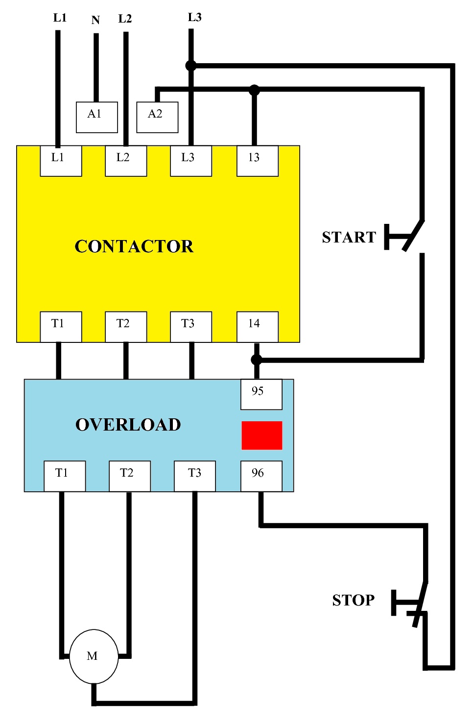
The wiring of direct on line control circuit starter is following. The induction motor draws a huge amount of current at startup.

Dol Starter Control Diagram Engineering Portal
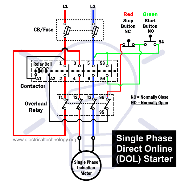
Direct online starter wiring diagram. Normally it gets one phase constant from incoming supply voltage a1when coil gets second phase relay coil energizes and magnet of contactor produce electromagnetic field and due to this. Dol starter of three phase induction motors control and power circuit consist mcb or fuse unit which connected in series with the supply. Three phase and single phase. A direct online starter consits of two buttons a green button for starting and a red for stopping purpose of the motor. Dol starter control diagram three phase. How to wire a contactor and overload.
And if you learn something from the diagram then also share this post. Use transformer if you need to. The ryb is the three phase 380 volts supply. Now if you have any question then use can use the below comments section. These two buttons ie. Power contactor thermal overload relay for protection and stop and start push button.
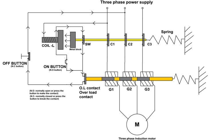
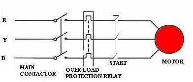
In the direct online starter animation diagram a 3 phase 440 volts supply is shown which is connect to the magnetic contactor main contacts. The contactor connection with thermal overload relay and the motor connection with overload relay is shown. Dol motor starter with 230v contactor coil. In the above dol starter diagram. Direct online starter dol diagram. Schematic and circuit diagram.
Dol starter for motors direct online starter diagram working types applications. Working principle of dol starter. I hope this three phase dol starter wiring or 3 phase motor wiring with direct online starter diagram help you. The main heart of dol starter is relay coil. Direct online starter circuit wiring diagram. This starting current can damage the motor windings.
The l1 contactor is connected from normally open no to r phase using mccb. You must watch this video. Direct on line starter. The dol starter comprises of an mccb or circuit breaker contactor and an overload relay for protection. Direct on line starter wiring diagram. The wiring diagram for a dol stater is shown below.
How to wire a contactor and motor protection switch. Wiring diagram of dol starter. From the blue wire a wire goes to the thermal overload relay normally close contacts and from there the wire goes to the contactor coil a1 terminal. Three phase motor control and design power circuit and installation. The coil of the contactor is 380 vac. In order to avoid any damage we use different techniques to reduce the starting current using motor starter.
And the normally open and normally close push button shown. Green and red or start and stop buttons control the contacts. Mccb wiring diagram for 3 pole 4 pole. The connection of contactor can be done among relay coil supply voltage as well as thermal overload.

