Do not connect or disconnect the wires. Refer to the example wiring diagram in this section.

Carrier 19xl Fig 51 Typical Wye Deltaunit Mounted Starter
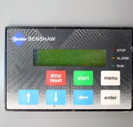
Benshaw soft starter wiring diagram. Soft starter main circuit wiring the soft starter is installed between the mains and cable to the motor. Reduced voltage starting and soft stopping. Page 196 runtest isolation switches test power plugs and wiring diagrams are available from benshaw. Be sure all ac power is removed from the soft starter before servicing. The standard connection of an electronic soft starter is 3 wire. This soft starter contains high voltage which can cause electric shock resulting in personal injury or loss of life.
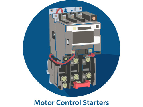
Full voltage reversing 3 phase motors. Enclosed product has wiring diagrams of associated control devices found within the enclosure. Induction motor is the most frequently used motor for industrial as well as domestic applications. The cost of this service is not included in the price of the benshaw soft starter and will be quoted specifically to each customers needs. Security starter relay controlled car starter wiring diagram. It uses two contactors two auxiliary contact blocks an overload relay a mechanical interlock two normally open start pushbuttons a normally closed stop pushbutton and a power supply with a fuse.
To ensure that the starter can stall automatically and the starter circuit not connected after the engine starts some cars adopt the compound relay circuit with safety driving protection. If a mains or isolation contactor is used it is best controlled by the soft starter line relay. Modbus rtu starter profibus dp network table 2. The security starter relay controlled car starter wiring diagram is as shown in the. There can be two types of control using soft starter. Benshaw bipc 300000 03 micro communications card rs485 rated 20 mhz for replacement in benshaw medium voltage starters.
In low voltage systems with an inlineisolation contactor. Soft starters are starting devices used for the acceleration deceleration and protection of the three phase electrical induction motors through the controlling applied voltage to 3 phase motor. You may get an electrical shock. The starter connector is used to connect the mxpb3 to a benshaw starter. Mostly industrial motors are single phase or three phase induction motor depends upon supply fed to it. Closed loop motor current control power.
This diagram is for 3 phase reversing motor control with 24 vdc control voltage. Profibus dp connector pinout pin profibus dp housing shield protective earth 1 not connected 2 not connected 3 b line rxtxd 4 rts request to send 5 gnd bus. Safety precautions electric shock prevention while power is on or soft starter is running do not open the front cover. An alternative connection is 6 wire or inside delta connection. Start up services benshaw technical field support personnel are available to do startup and conduct on site training on the starter operations and. A start voltage is applied with time irrespective of the current drawn or the speed of the motorfor each phase two scrs are connected back to back and the scrs are conducted initially at a delay of 180 degrees during the respective half wave cycles for which each scr conducts.


