A wiring diagram is a simplified conventional photographic representation of an electrical circuit. Using a small inductive pickup strapped to the alternator these units are easily calibrated to read rpm quickly and accurately just as youd expect from and autometer tach.

Pro Tach Tachometer Wiring Gain Kobe Afcev De
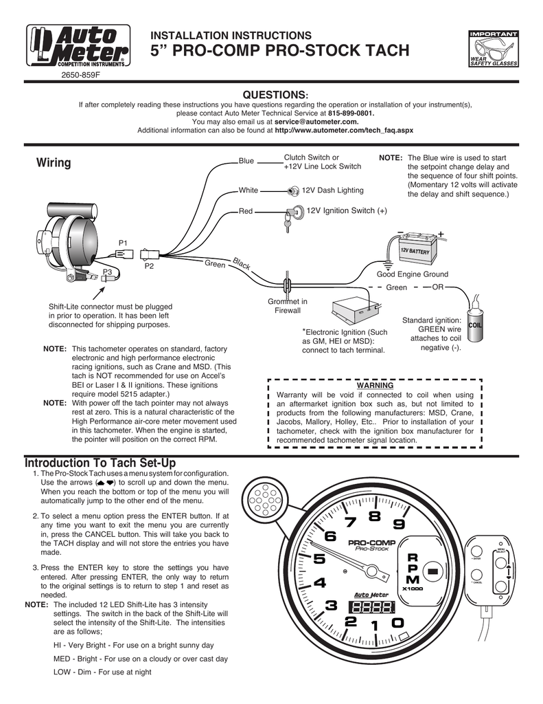
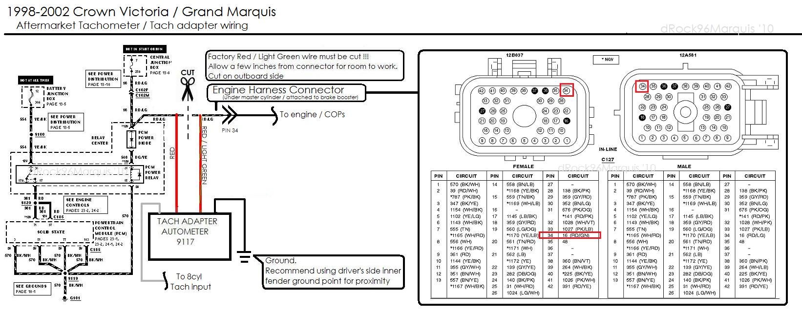
Autometer rpm wiring diagram. Assortment of autometer gps speedometer wiring diagram. Its intended to aid all the average person in developing a suitable method. The wiring diagram shown is a typical installation. It shows the components of the circuit as streamlined shapes as well as the power as well as signal connections in between the devices. Autometer tach wiring diagram wiring diagram collection. Set the desired rpm by turning the adjust.
Warrants to the consumer that all auto meter high performance products will be free from defects in material and workmanship for a period of twelve 12 months from date of the. Autometer has designed their tach to be used with four six. Click on the image to enlarge and then save it to your computer by right clicking on the image. Both black wires are interchangeable and can be used for any of the listed purposes. The auto meter 2888 and 3788 diesel tachs will work out of the box with your diesel engine. This signal can then be used to drive any standard autometer tachometer.
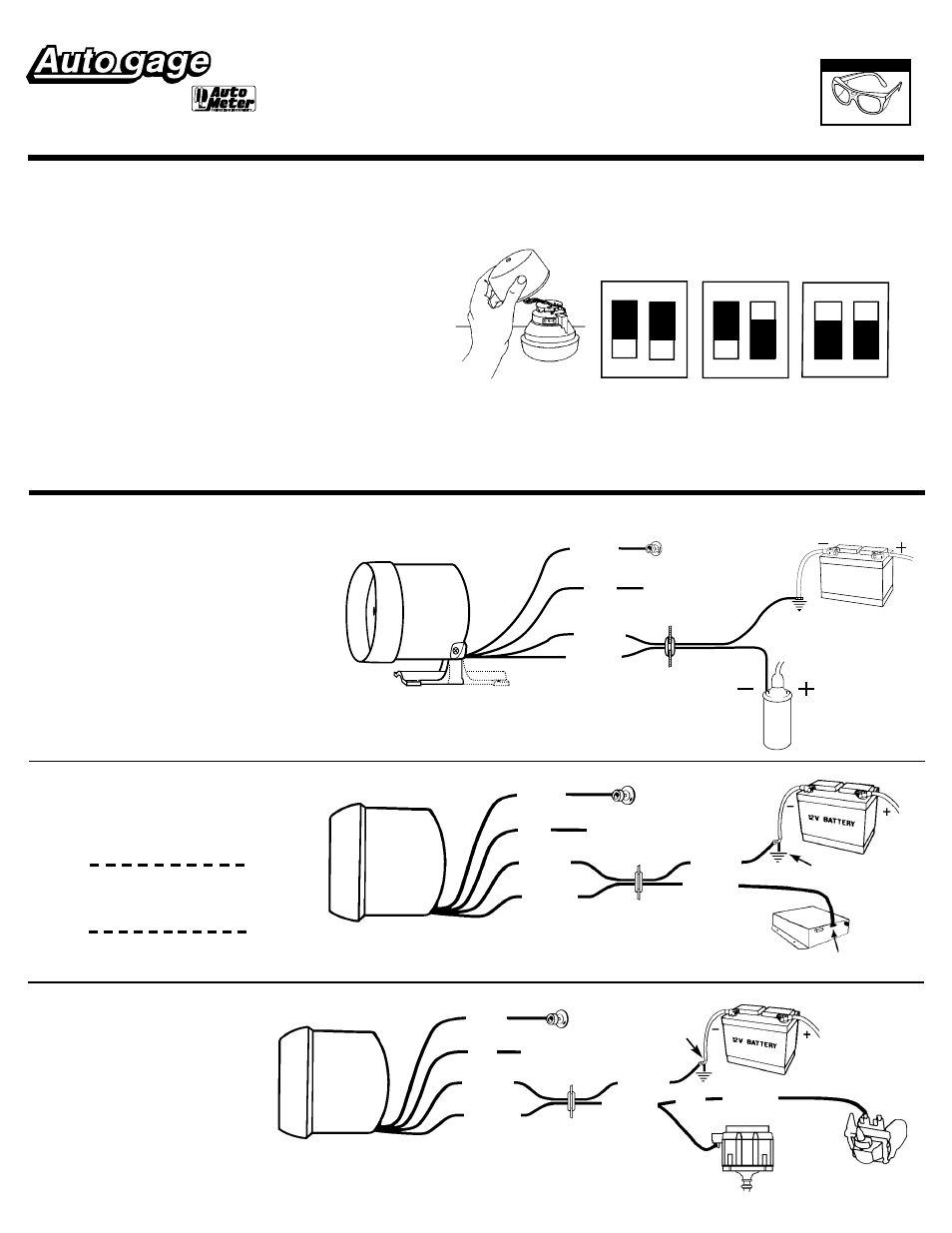
Mount probe trigger on alternator by centering trigger over. For chrysler blue gold and silver boxes ford standard electronic. Rpm signal will provide a 12v square wave output with an equivalent 4 ppr tach signal. Horsepower for example 3400 rpm. Gage model 2302 tachometer when used with auto meter model 5215 beilaser adapter. Auto meter products inc.
Turn on the power to the tach. Variety of autometer tach wiring diagram. Laser il with date code of 8100 or higher. The wiring diagram shown is a typical installation. Auto meter tach wiring diagram at autometer autometer tach wiring. Figure a for chrysler blue gold and silver.
Wiring your new autometer tachometer into your car will complete the installation. Once you have selected a mounting location you can run the four wires that operate the tachometer. Wiring diagram arrives with several easy to follow wiring diagram guidelines. Rpm x1000 by 180. Autometer pro comp ultra lite wiring diagram fresh auto meter wiring autometer gauge wiring diagram. The tachometer is designed to show the engine rpms or rotations per minute.
These guidelines will be easy to understand and apply. Wiring operation installation 1.


