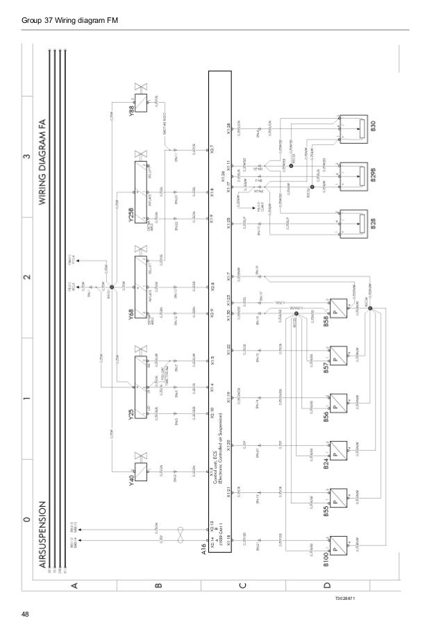
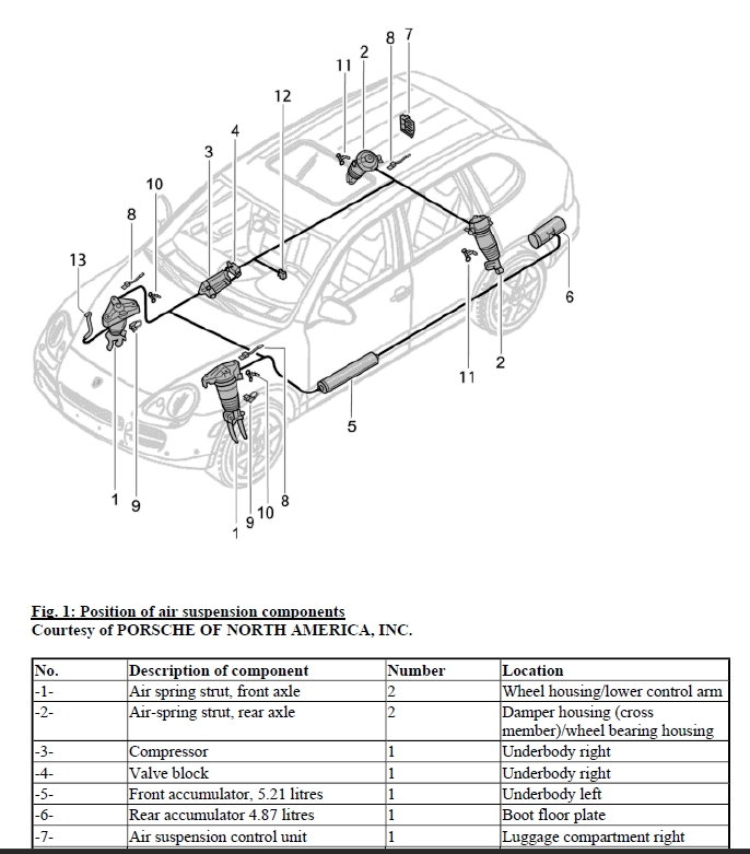
A91 29 l airmatic compressor unit a91m1 30 l air compressor motor a91y1 29 l airmatic pressure reduction valve b223 61 l rear axle level sensor b228 15 l left front level sensor b229 18 l right front level sensor b243 10 l left front body lateral acceleration sensor. Which air lift products fit your ride.
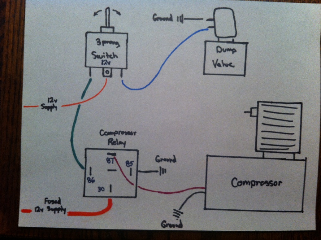
E5bfc93 Air Ride Compressor Wiring Diagram Wiring Resources
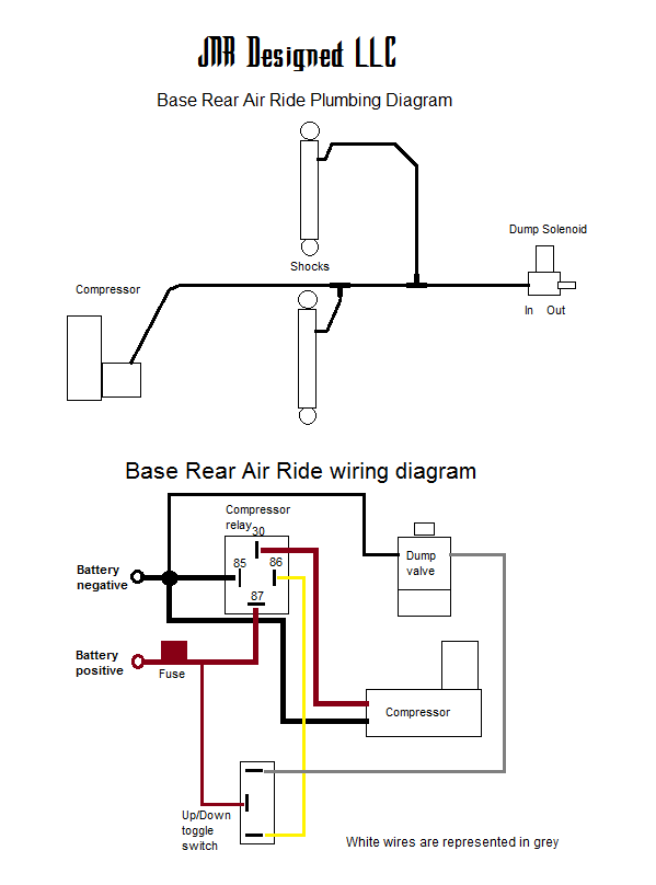
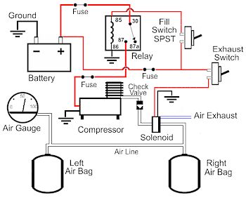
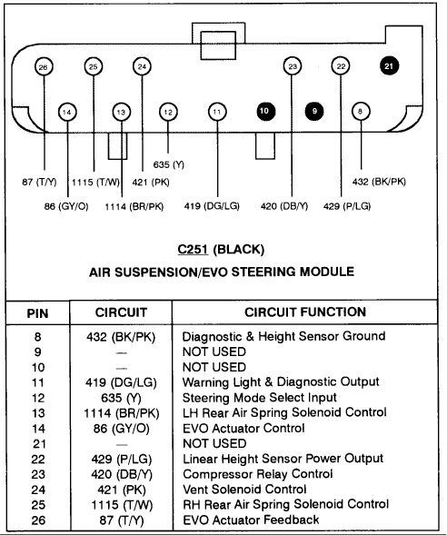
Air suspension wiring diagram. Arnott air suspension installation manuals for luxury cars trucks and suvs. There is the chance of a blown fuse for the air compressor pump. 2020 2019 2018 2017 2016 2015 2014 2013 2012 2011 2010 2009 2008 2007 2006 2005 2004 2003 2002 2001 2000 1999 1998 1997 1996 1995 1994 1993 1992 1991 1990 1989 1988 1987 1986 1985 1984 1983 1982 1981 1980 1979 1978 1977 1976 1975 1974 1973 1972 1971 1970 1969 1968 1967 1966 1965 1964 1963 1962 1961 1960. These wiring diagrams cover all c model viair compressors as included with our manual air ride management kits. Faulty relay or blown fuse the air suspension compressor relay is known to fail. It could either not engage the air suspension compressor at all or even worse keep it engaged for longer that required.
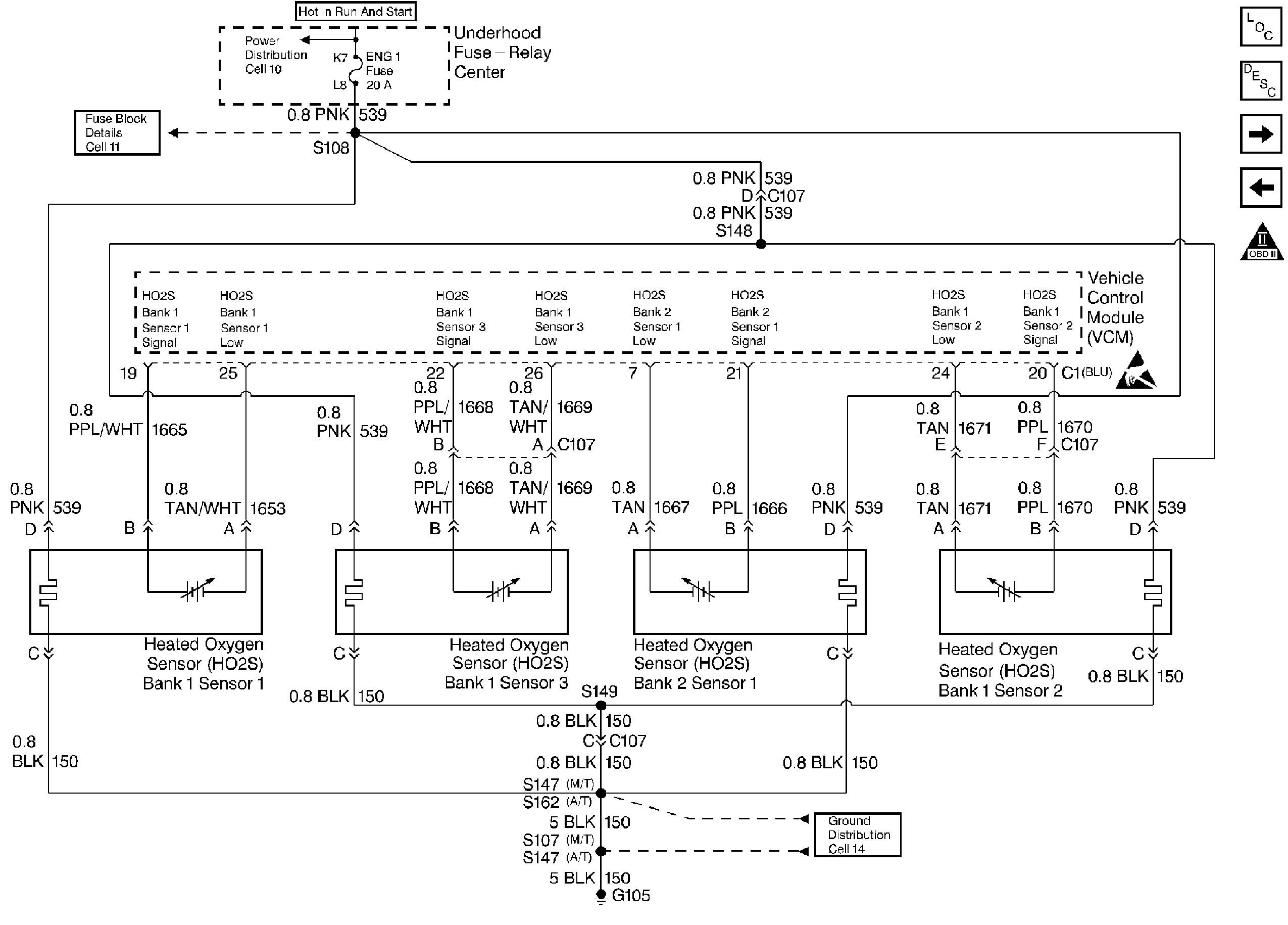
Using 8 guage power wire with 50 amp fuse dc75007600 within 6 of battery 30amp fuse for dc2500380 route to circuit breaker or terminal 30 on relay. A wiring diagram is a streamlined standard photographic representation of an electrical circuit. Air suspension dump valve schematic wiring diagram database. It reveals the components of the circuit as streamlined shapes as well as the power and also signal links between the gadgets. If the air suspension compressor is kept engaged for too long it can get damaged. Air suspension dump valve schematic the wiring diagram on the opposite hand is particularly beneficial to an outside electrician sometimes wiring diagram may also refer to the architectural wiring program the simplest approach to read a home wiring diagram is to begin at the source or the major power supply basically the home wiring.
Assortment of air bag suspension wiring diagram. Wiring diagram of airmatic control unit code. Run air line from valves to bags cylinder or airstruts and label valves to show assigned corner that valve is feeding. Air suspension compressor diagram the wiring diagram on the opposite hand is particularly beneficial to an outside electrician sometimes wiring diagram may also refer to the architectural wiring program the simplest approach to read a home wiring diagram is to begin at the source or the major power supply basically the home wiring diagram is simply utilized to reveal the diyer where the. Use the following diagram for twin compressor setups. We recommend all items are installed by a qualified individuals.
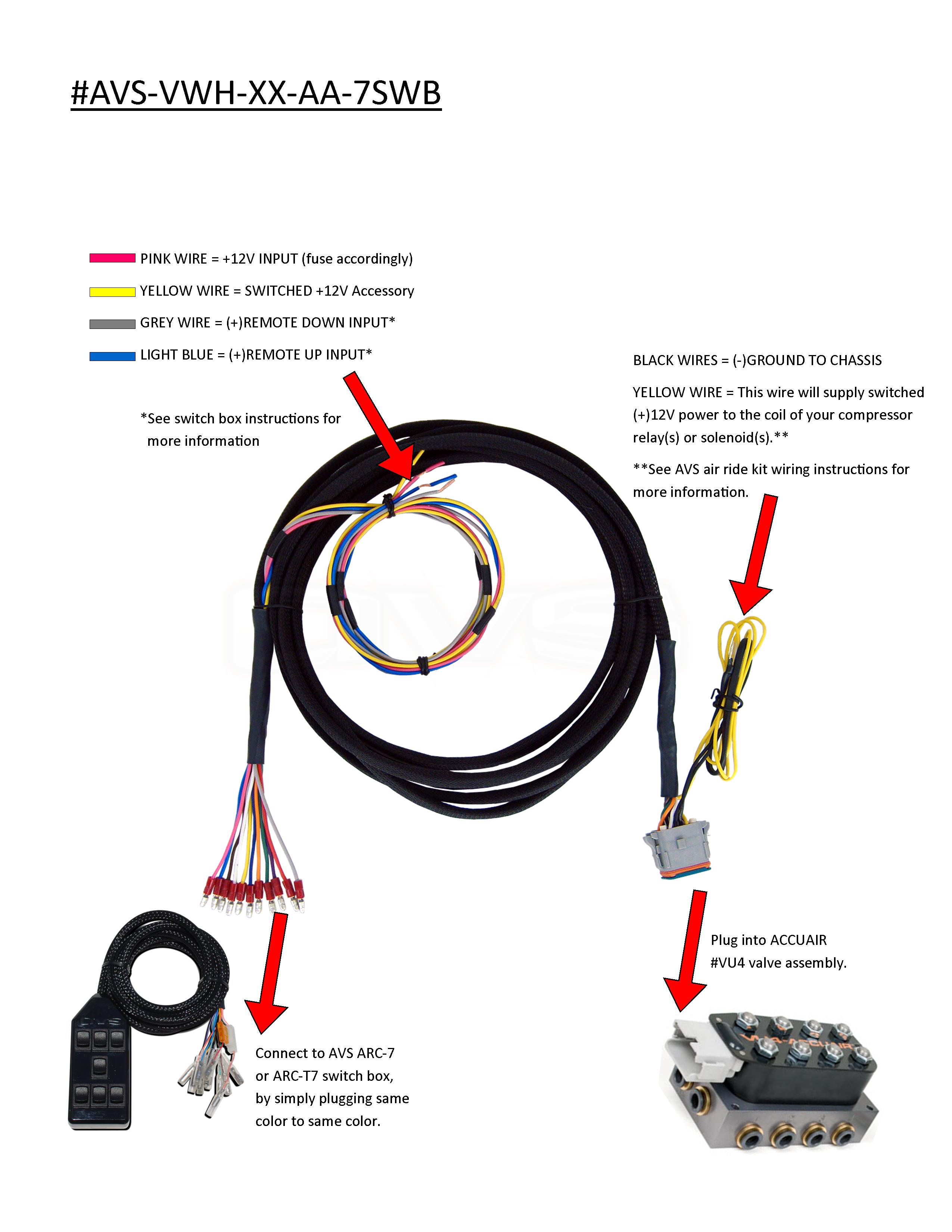
Air ride manual 4 valve management system wiring diagram for most manual operated air ride systems.
