In the interim please contact technical support. When you wire dual voice coils and multiple subs together the resulting total impedance is not always simple to figure out or practical to use.

All In One In Dash Gps Multimedia Units Reduce The Risk Of
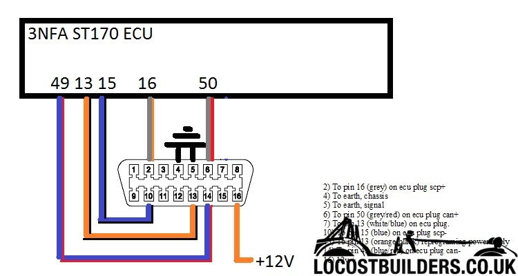
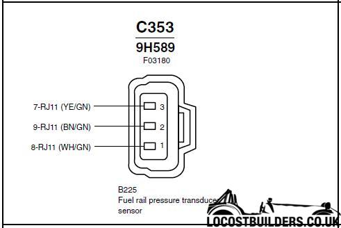
Woza cable wiring diagram. Wiring a gfci outlet with a light switch. Trailer wiring diagram wiring diagrams for trailers international 1 989 755 0561 toll free 1 800 358 4751 covid 19. The source is at sw1 and the hot wire is connected to one of the terminals there. How to wire gfci combo switch and outlet gfci switchoutlet wiring diagrams. 1 718 816 8112 monday through friday 1100 am 300 pm eastern time or email. In this diagram 2 wire cable runs between sw1 and the outlet.
Tow vehicle taillight wiring 2 wire system. The following picture shows the wiring diagram of the two standards. If you are an existing customer and have questions about your wiring or connection please call 780 450 6787 email. Some diagrams may be unavailable during this time. To connect the electric system of your trailer to the vehicle you will be using special connector. Below is the generic schematic of how the wiring goes.
Youll love our internet and hosting services. Some vehicles use a combination bulb dual filament for turn and stop. This way the switch and light bulb is gfci protected. Tow vehicle has same bulb for lighting stop and turn signals. The other switch terminal is connected to the black cable wire running to the hot terminal on the receptacle. Use this handy trailer wiring diagram for a quick reference for various electrical connections for trailers.
However for the crossover wiring method the rj45 pinouts on each end of the cat5e are different. In the first diagram the single way switch and light bulb is connected to the load terminal of gfci. Email protected we endeavor to reply to most emails by the next business day. When you are doing the straight through wiring the cable pinout on the two ends of the cat5e cable should be the same. 5 wire trailer wiring diagram. Wiring capacitors resistors semiconductors table 1 standard elementary diagram symbols contd iron core air core auto iron core air core current dual voltage thermal magnetic single phase 3 phase squirrel cage 2 phase 4 wire wound rotor armature shunt field show 4 loops series field show 3 loops commutating or compensating field show 2.
Ethernet cable color coding diagram for. Above we have describes the main types of trailer wiring diagrams. The following picture shows how the eight wires are used. Whether you need to use a series wiring configuration parallel wiring or a mix of both our diagrams will show you exactly the best way to wire your speakers. Use a simple 4 way flat connector to power your 2 light trailer lights or use a custom vehicle specific trailer wiring harness. Our apologies for the inconvenience.
