Pedal force graph load circuit diagram 011161 12102014 all sh2 c5sh2 c5 c 1 updated titleblock 2item 13 402970 was 402522 3 item 12 400179 was 401622 011806 06052015 3rd angle projection this document is property of and contains the proprietary information of williams controls industries inc. Electronic hydraulic and pneumatic throttle controls configurable joysticks adjustable pedal systems sensors hand controls and armrest systems for use on all types of commercial vehicles.

Curt 51110 Venturer Electric Trailer Brake Controller Time Delay
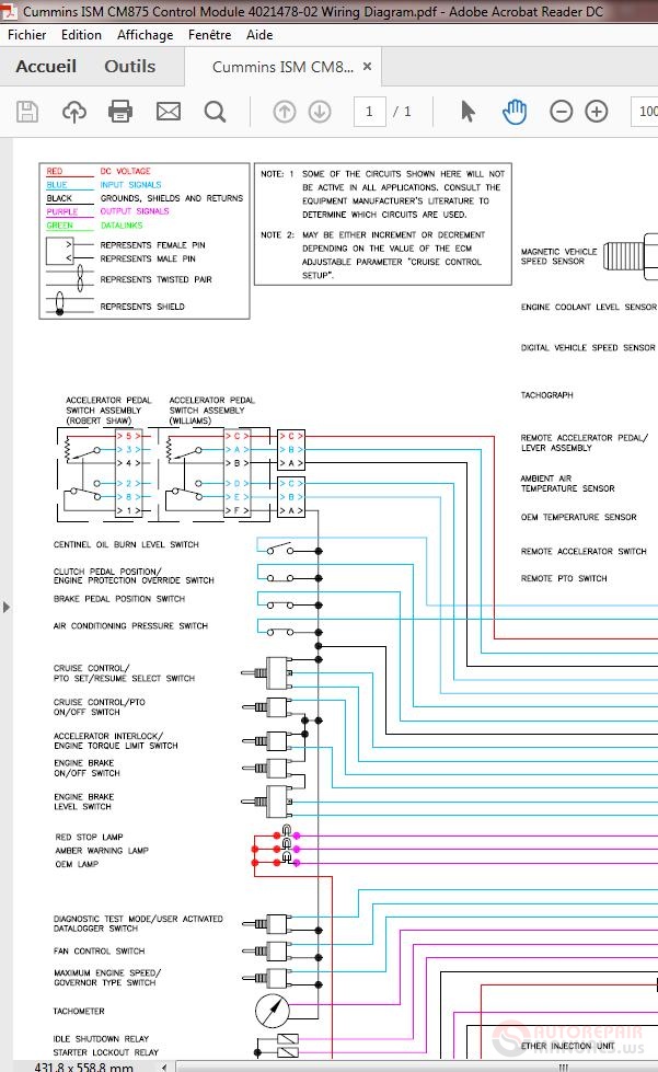
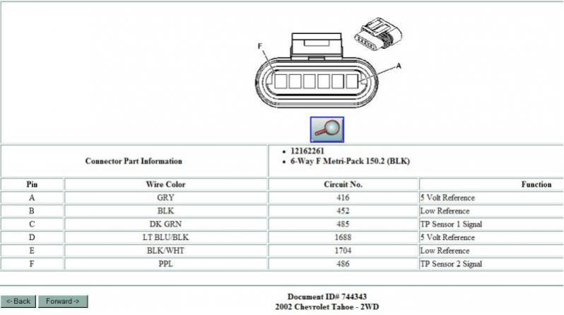
Williams controls accelerator pedal wiring diagram. The accelerator position sensor varies the signal voltage to the electronic control module ecm as the accelerator pedal is depressed and released. Wm476c d 68 pneumatic throttle pedal alternate substitution wm476f5a2 wm476f5a1 b 70 pneumatic throttle pedal wm117209 wm476f5a2 d 70 pneumatic throttle pedal wm130634 wm499c d 72 relay air start wm113470 wm511c c 74 hydproportional pedal wm119130 wm512c c 76 hyd throttle cylinder wm119436 wm513a b 78 qr. The products are the legacy of the williams controls company founded in 1937 and acquired by curtiss wright in 2012. Low signal voltage is received by the ecm when the accelerator pedal is at 0 percent. It is also nick named as a tps sensor used on widely on about 95 of heavy duty trucks. Williams controls products comprise.
49 8104 628 7820 wwwwmcoeu document number 401207 rev. 14100 sw 72nd avenue portland oregon 97224 usa phone. Andor its subcontractors and. A high signal voltage is received by the ecm when the accelerator pedal is at 100 percent. 49 8104 628 7810 fax. This is a electronic throttle control kit or throttle positioning sensor kit made by willaims controls.
A 211 2011 by williams controls. 1 503 684 8600 fax. This procedure is a mute point if you have the wiring diagram but often times you just need to actuate the electronic throttle to do a cleaning and run the electronic throttle t p s though the.


