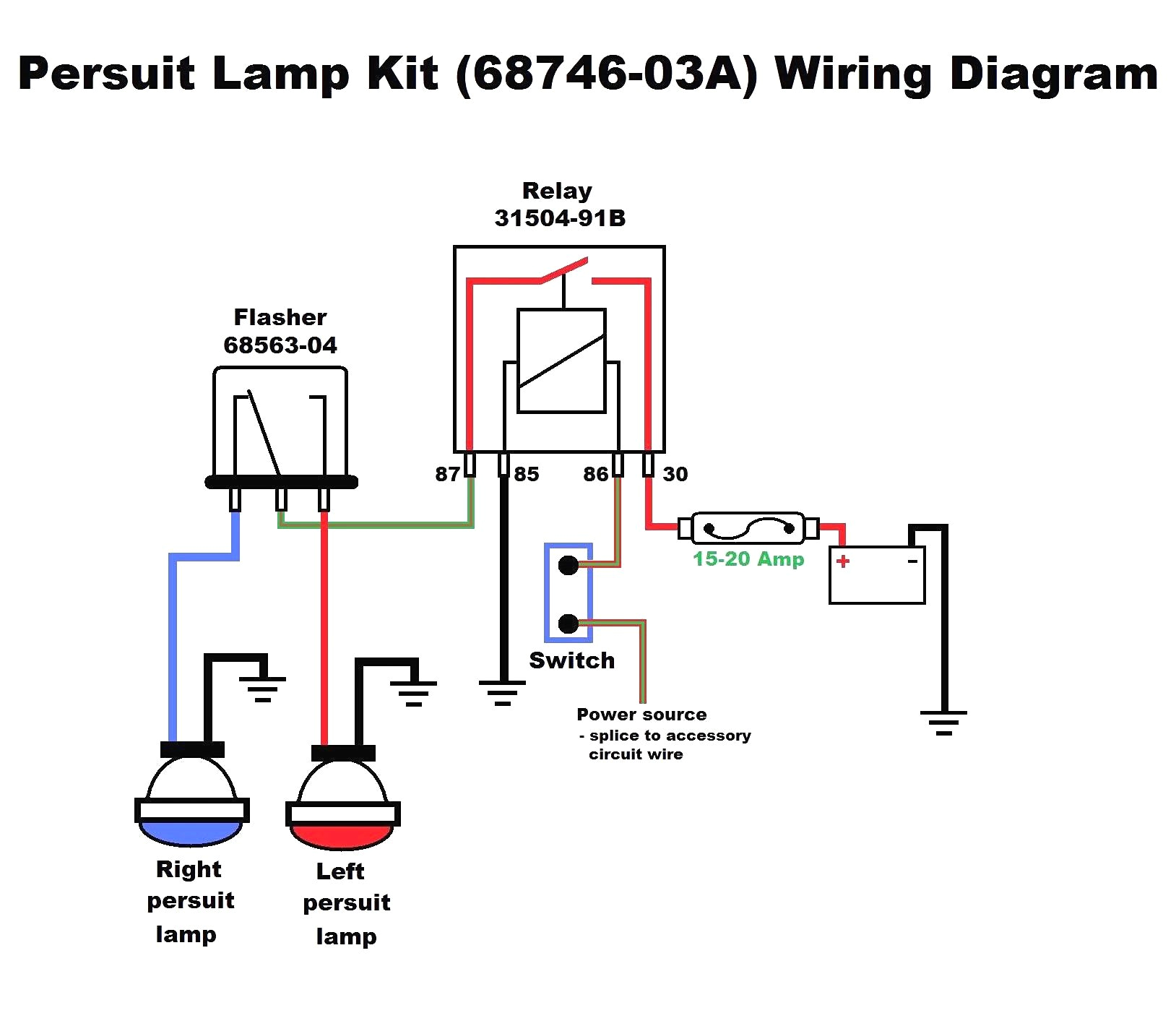
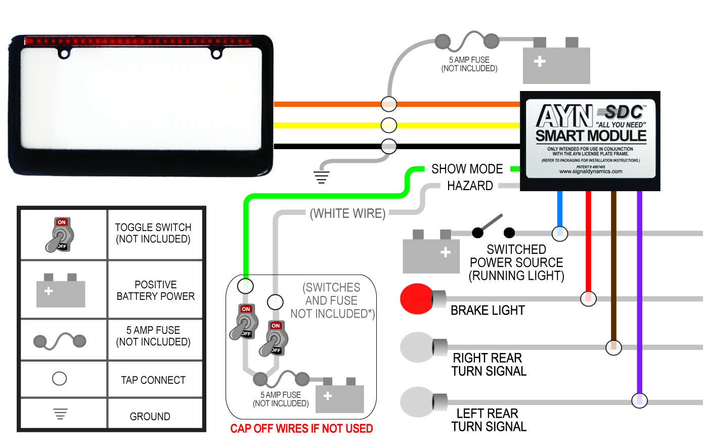
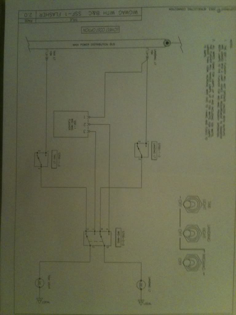
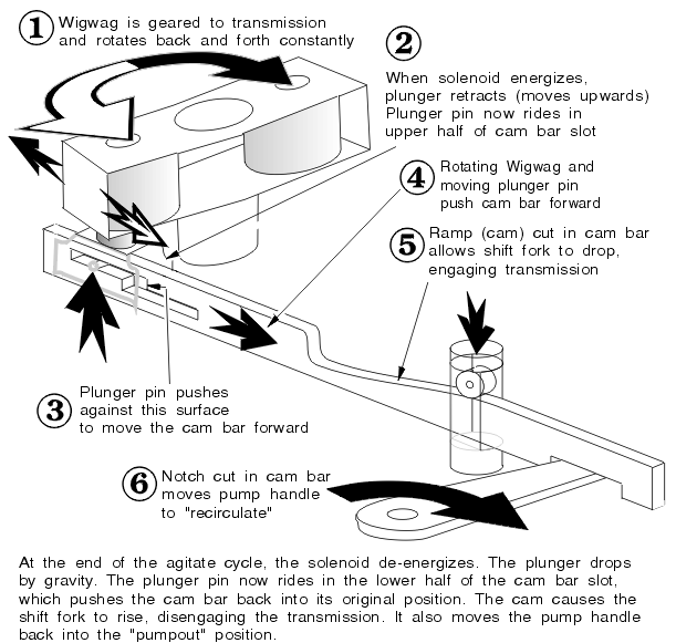
C wig wag operation is commanded by moving the switch from off to full up without delay. Connect as shown in diagrams.

Dl 3173 568 Jpeg 30kb Wig Wag Wiring Diagram Whelen Uhf2150a
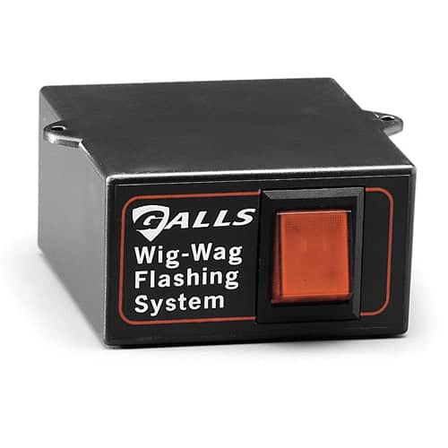
Wig wag wiring diagram. Happy reading wig wag flasher wiring diagram book everyone. Wig wag flasher wiring diagram book. Galls wig wag flasher with built in switch. It shows the components of the circuit as simplified shapes and the knack and signal contacts in the company of the devices. Galls wig wag flasher wiring diagram 3 pin flasher relay wiring diagram galls wig wag flasher wiring diagram wiring diagram is a simplified within acceptable limits pictorial representation of an electrical circuit. Ef30al model 1 created date.
Part 01009 backoff wig wag brake light module for gl1800. Yellow brown wires. This one piece unit with built in switch mounts conveniently inside your vehicle. Connect the fused red wire to the vehicles battery positive post making sure the switch is in the off no light position. 06112018 06112018 1 comments on whelen wig wag wiring diagram a modification to the standard headlight wiring harness. Alternating flash pattern produces 2 flashes per second for eye catching additional warning power.
The high beams will alternately flash wig wag and normal high beam operation is interrupted. Rated load 20ma to15a uncontrolled. Email protected disconnect the battery from the electrical system before attempting any part of this installation. Home made wigwag headlight flasher just using 3 change over relays and a flasher unit for blinkers. Ef30al circuit diagram flasher p wire 30a x l fuse left right battery see note see note note. Installation and operation manual aec series programmable wig wag controller.
Mode a operation is the wiring diagrams illustrate a two switch option. 682011 13628 pm. Turns ordinary headlights into a wig wag flashing system. Wigwag flashing lights positive inputpositive output relay wiring diagram by placing a load on the flasher with a hidden 12v light bulb power resistor or rheostat the flasher will cause the coil of the top relay to energize and de energize and in turn alternate 12v to each light for as long as terminal 86 of the bottom relay is connected. All customer supplied wires that connect to the customer service e mail. Universal wiring diagram for all led light bars with turn signals part varies led bullet lights base mount part varies led bullet lights bolt mount part 0272202723 ayn license plate frame and smart module.
