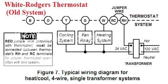
It is not used on systems without a transformer or relay hot water heat systems that use 3 wire zone valves two stage heating or. White rogers thermostat wiring diagram white rodgers thermostat wiring diagram white rodgers thermostat wiring diagram 1f78 white rodgers thermostat wiring diagram 1f79 every electrical arrangement is composed of various unique components.

Page 3 Of White Rodgers Thermostat 1311 User Guide
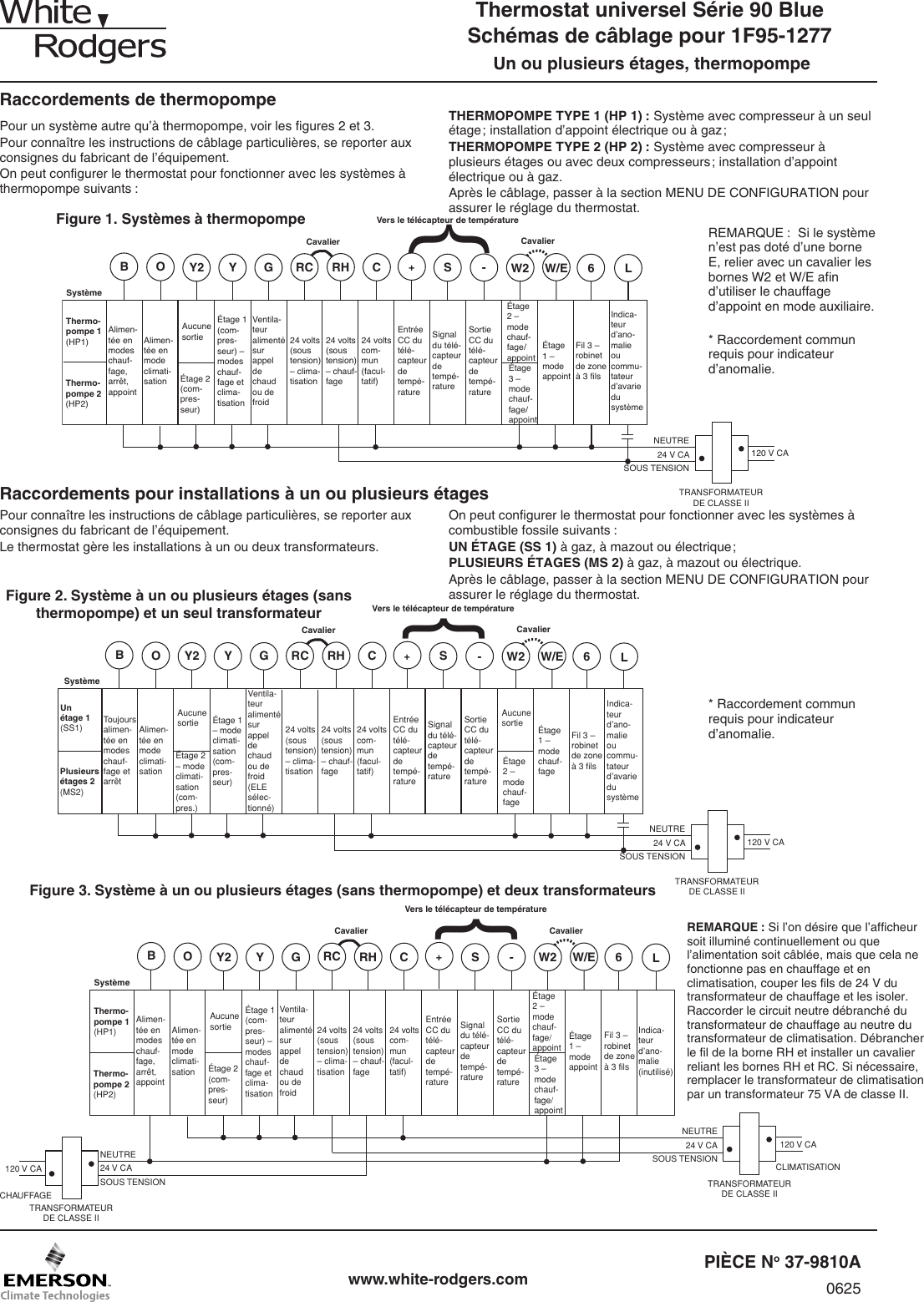
White rodgers thermostat wiring diagram. White rodgers is a leading manufacturer of thermostats valves controls and system protectors for the heating air conditioning and refrigeration industry. Wiring instructions for change rodgers 1f thermostat to honeywell rthlrthl series thermostat. Old used 6 answered by. A wiring diagram is a streamlined traditional pictorial depiction of an electric circuit. Drill holes and insert wall anchors to. This article provides room thermostat wiring diagrams for flair honeywell white rodgers and other thermostat brands.
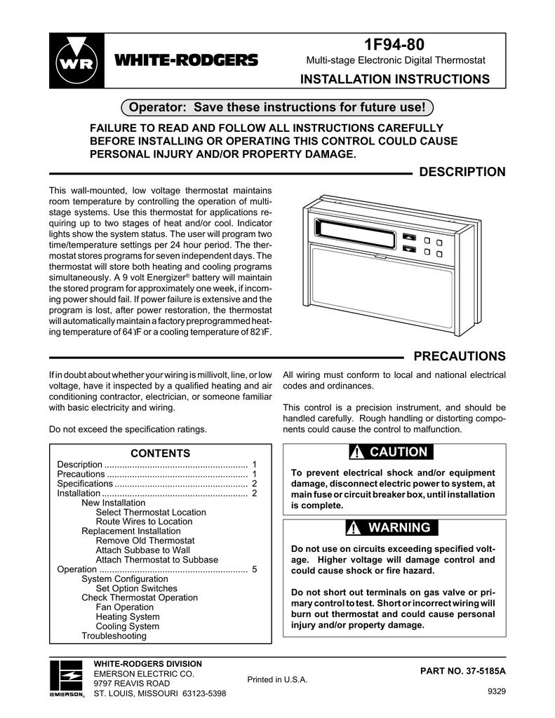
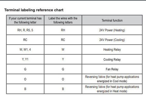
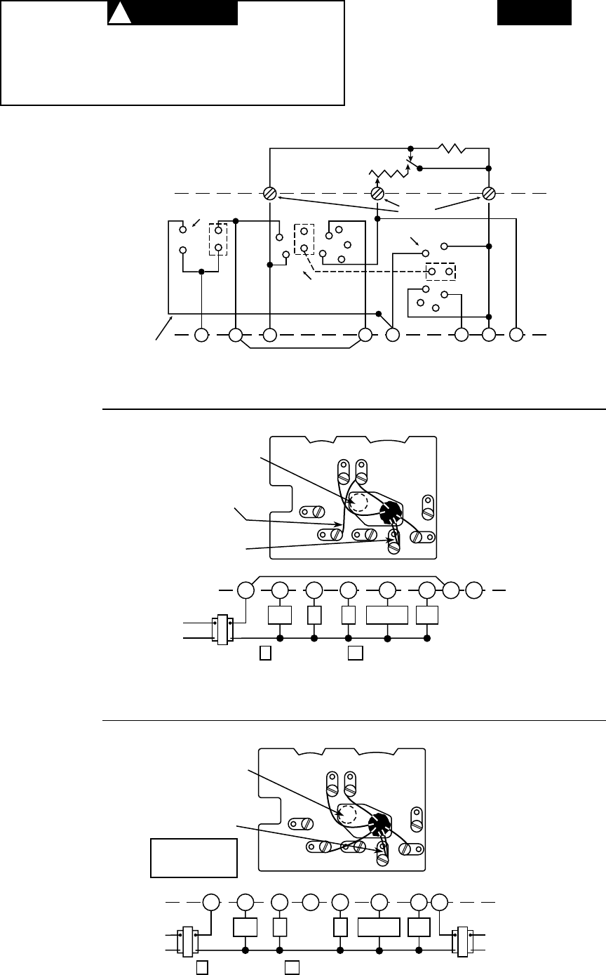
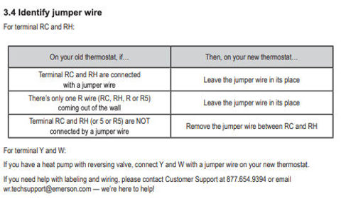
White rodgers division reversing valve can be controlled by the wiring selection. If you have a white rodgers heat pump and thermostat system or an a diagram of the wire terminals and indicate which wires go where. Each part ought to be set and connected with different parts in particular manner. The white rodgers 1f90 and similar models will replace most 2 wire heating thermostats and many 3 wire 4 wire thermostats used for both heating and cooling. If you have a white rodgers heat pump and thermostat system or an emerson thermostat the wiring likely follows a particular pattern. If you are installing a new thermostat refer to the manufacturers instructions.
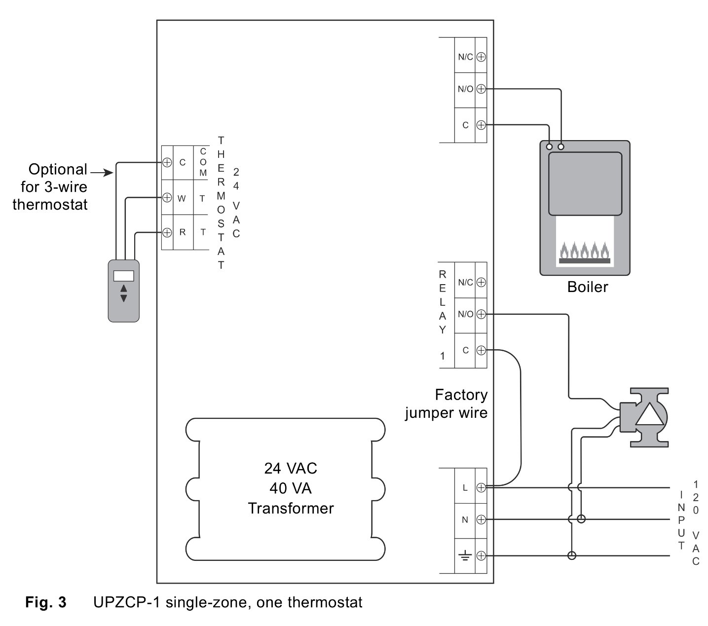
Wellborn assortment of white rodgers thermostat wiring diagram. White rodgers thermostat wiring diagrams drawings. It reveals the parts of the circuit as streamlined forms and the power and signal connections between the devices. They should contain a diagram of the wire terminals and indicate which wires go where. October 17 2018 by larry a.
