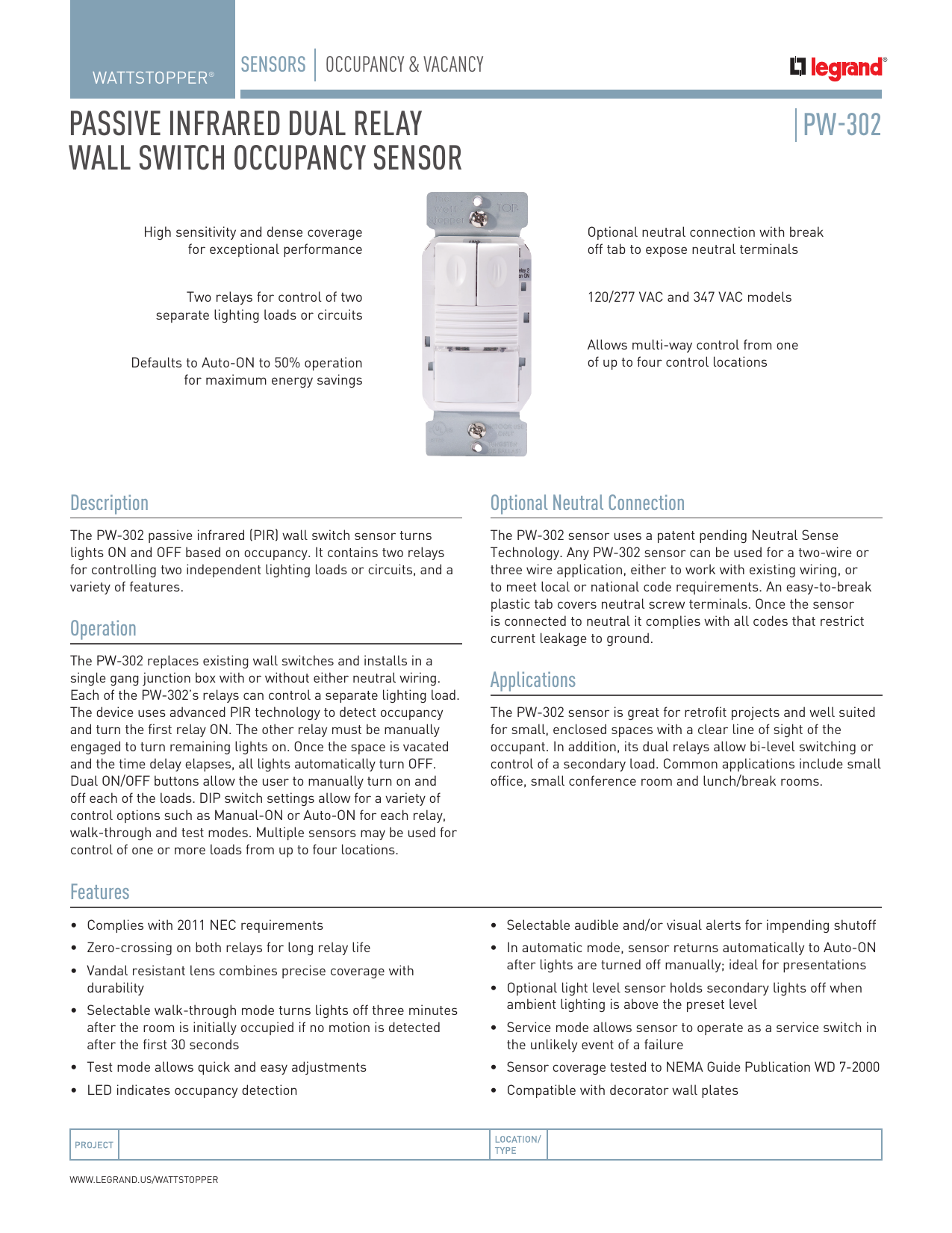
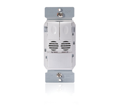
The dsw 301 dual technology wall switch occupancy sensor turns lights off and on based on occupancy. Watt stopper ts 400 w u inteliswitch digital time switch 100 277vac 5060hz 40 out of 5 stars 1.

2013 Stand Alone Solution Legrand
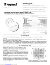
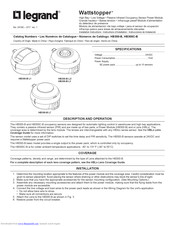
Wattstopper dsw 301 wiring diagram. Wattstopper dsw 301 accessories pdf manual download. All units should be on the same phase. View and download legrand wattstopper dsw 301 user manual online. Toggle industrial grade non grounding back side wiring white 46 out of 5 stars 3. Watt stopper dsw 301 w u dual tech wall switch occupancy sensor 120277vac 5060hz white. Wattstopper dsw 301 347 wattstopper dsw 302 347 wattstopper dsw 302.
Wiring a bz 150 universal voltage power pack duration. Dsw 302 and dsw 302 347 bi level wiring dsw 302 and dsw 302 347 dual circuit wiring warning turn the power off at the circuit breaker before installing the sensor or working on the load. Dual technology multi way wall switch occupancy sensor. 5060hz 16 hp at 120vac 0 1000w ballast led and tungsten. Dual technology multi way wall switch occupancy sensor 12 pages. The dsw 301 replaces existing wall switches and fits behind a standard decorator wall plate.
Model and electrical supply. 41 x 158 x 139 1046mm x 403mm x 355mm pw 301 347. 12 14 awg cu wire only 12 127mm black red load neutral line green green neutral optional ground yellow dsw 301 and dsw 301 347 wiring black red. Wattstoppers dual technology has the flexibility to work in a. The ground wire green must be fastened to ground for the sensor to work properly. Legrand wattstopper dsw 301 user manual.
The dsw 301 dual technology wall switch sensor turns lights. Wattstopper products services 41218 views. Coverage pattern wiring diagrams multi way wiring note. For best performance wattstopper recommends. Shown in the applicable wiring diagram for the sensor module. For the love of physics walter lewin.
82014 ordering information specifications dsw 301. Accessories legrand wattstopper dsw 301 user manual. 3 or 4 conductor 18awg stranded ul style 2517. Connect wires to the dsw flying leads as shown in the wiring diagram that is appropriate to the dsw. 45 x 158 x 139 11436mm x 403mm x 355mm ul and cul listed five year warranty product controls neutral option dip switch settings coverage pattern wiring diagrams delay walk pir 50 trigger alerts rly 1 man rl y 2 man dip switches detection. It combines the benefits of passive infrared pir and ultrasonic detection technologies.


