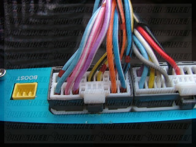
9 vanderbilt irvine ca 92618. If there are any questions regarding this products please contact your greddy authorized dealers or greddy performance products inc.
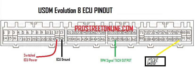
How To Install A Greddy Emanage In A Evolution 8
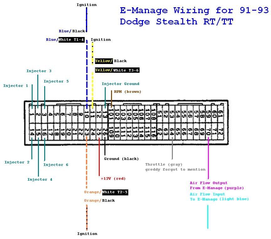
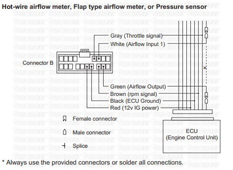
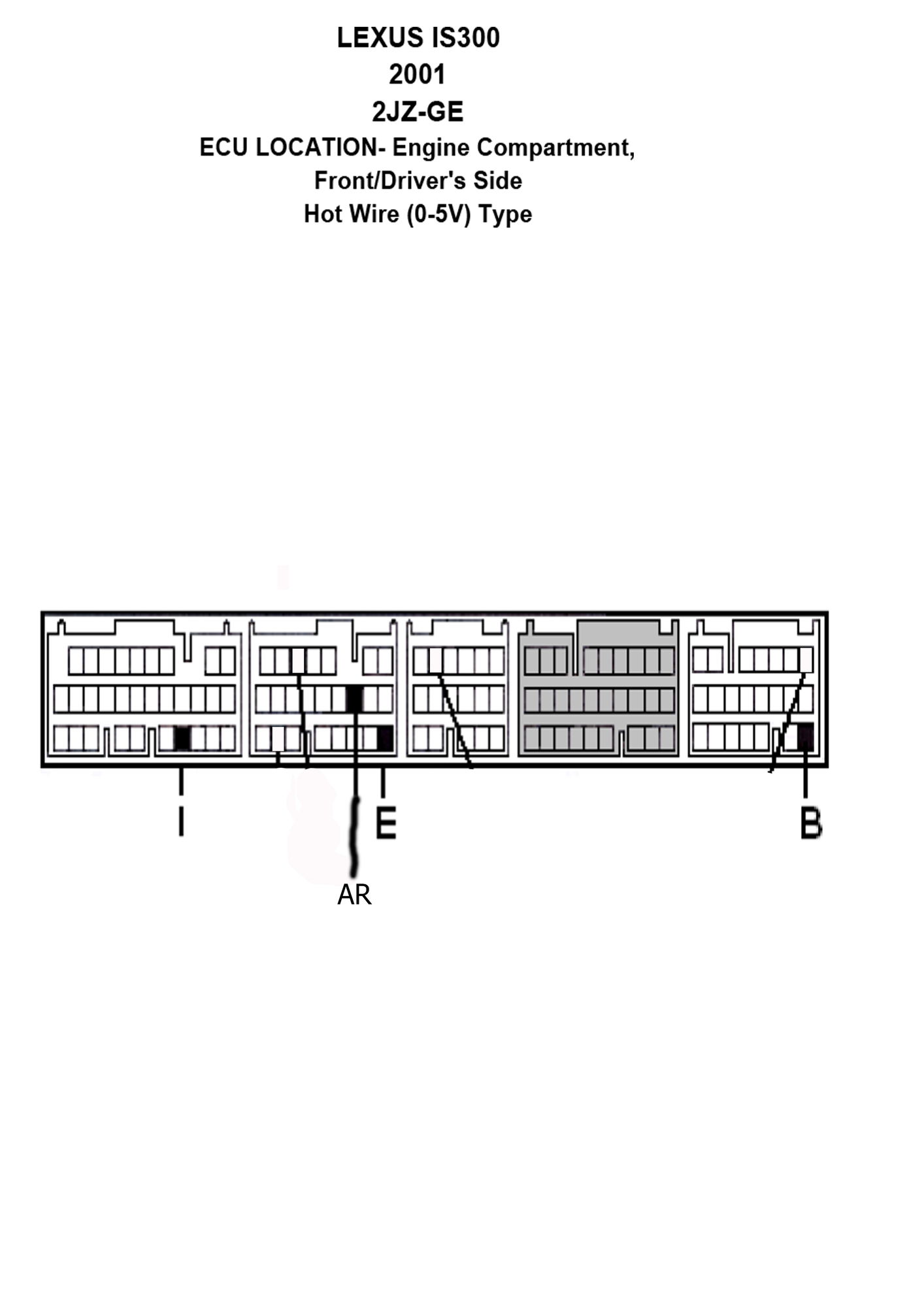
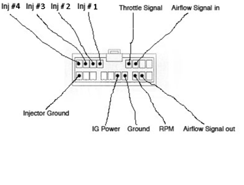
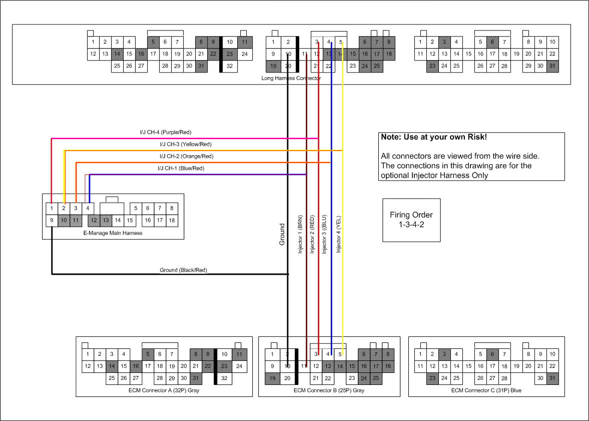
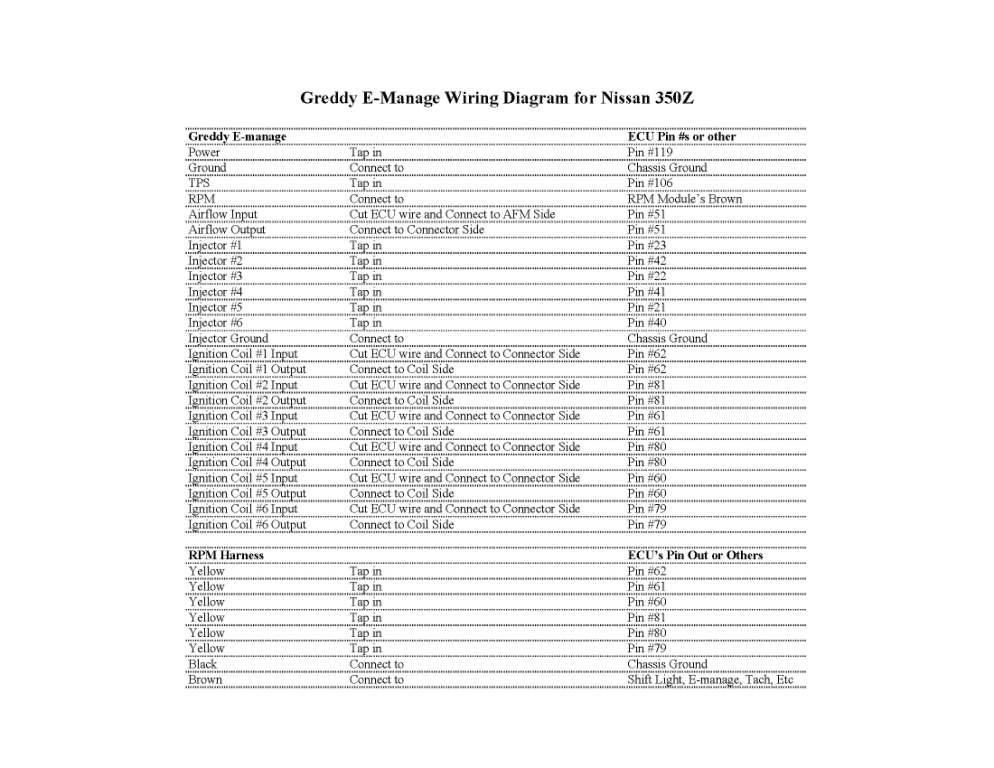
Greddy emanage blue wiring diagram. Emanage operation wire signal emanage connector emanage wire color ecu pinout ecu wire color connection type power red 102 or 107 red t solder ground black 101 or 106 black t solder rpm brown 21 black t solder throttle grey 19 greenwhite t solder airflow input light blue 10 from mas greenblue connector. This is a sure way to do that. When connecting the connector push it in all the way until you hear them click in together. I used the info in the greddy manual and supplements to draw up the above diagram so if you want to figure out the wiring for an ep82 this is how i did it. Well i just had my emanage mapped with it being fitted according to the wiring diagram above so anyone wanting to wire in an emange to their glanza then they can use this diagram to help. A laptop win98se pii with 196mg or better greddy support tool and a cable.
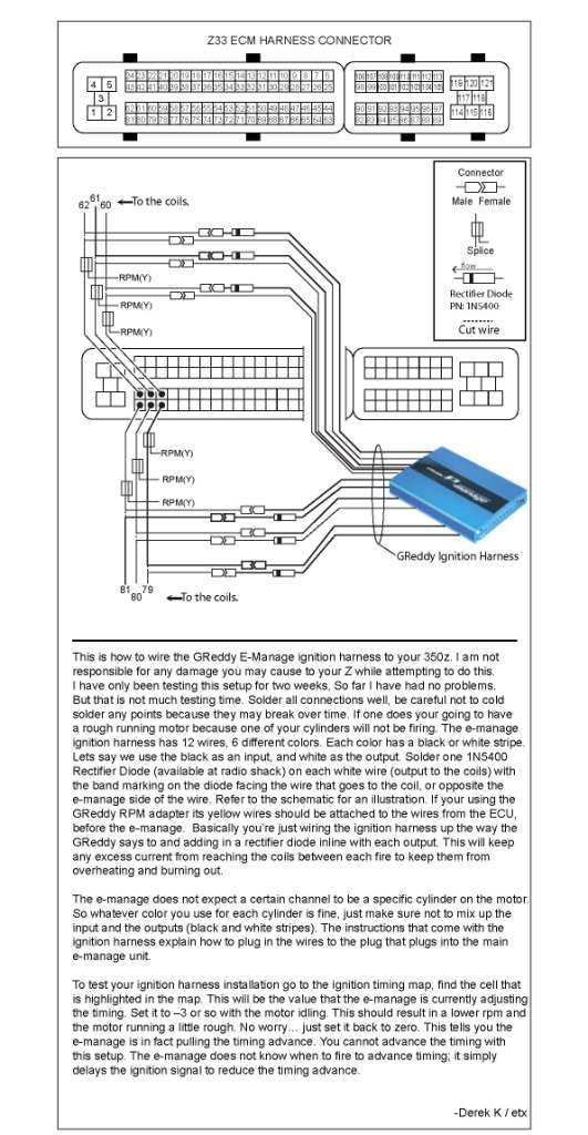
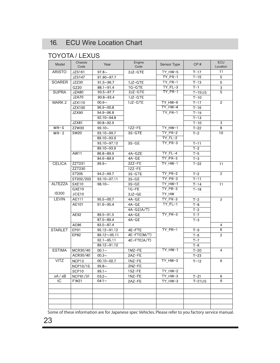
E manage blue installation verification before strapping your rig to a dyno or hitting the track every effort should be taken to insure the e manage is working correctly. Read and fully understand the wiring diagram before making any wire connection. Greddy greddy emanage blue wiring diagram greddy emanage blue wiring diagram schematron g reddy emanage blue wiring diagram wiring diagram database greddy e manage ultimate installation manual download installation greddy greddy e manage jdm manuals.
