Page 21 installation wiring vcb x controller output wiring vcb x controller outputs also please note that when wiring the vcb x controller its contacts must be wired as wet contacts connected to 24 vac. Rear view camera can not work suddenly it is also check whether the line is loose or check whether the backup camera has been damaged.

Pic Upgraded Frc Control System Wiring Diagram Cd Media
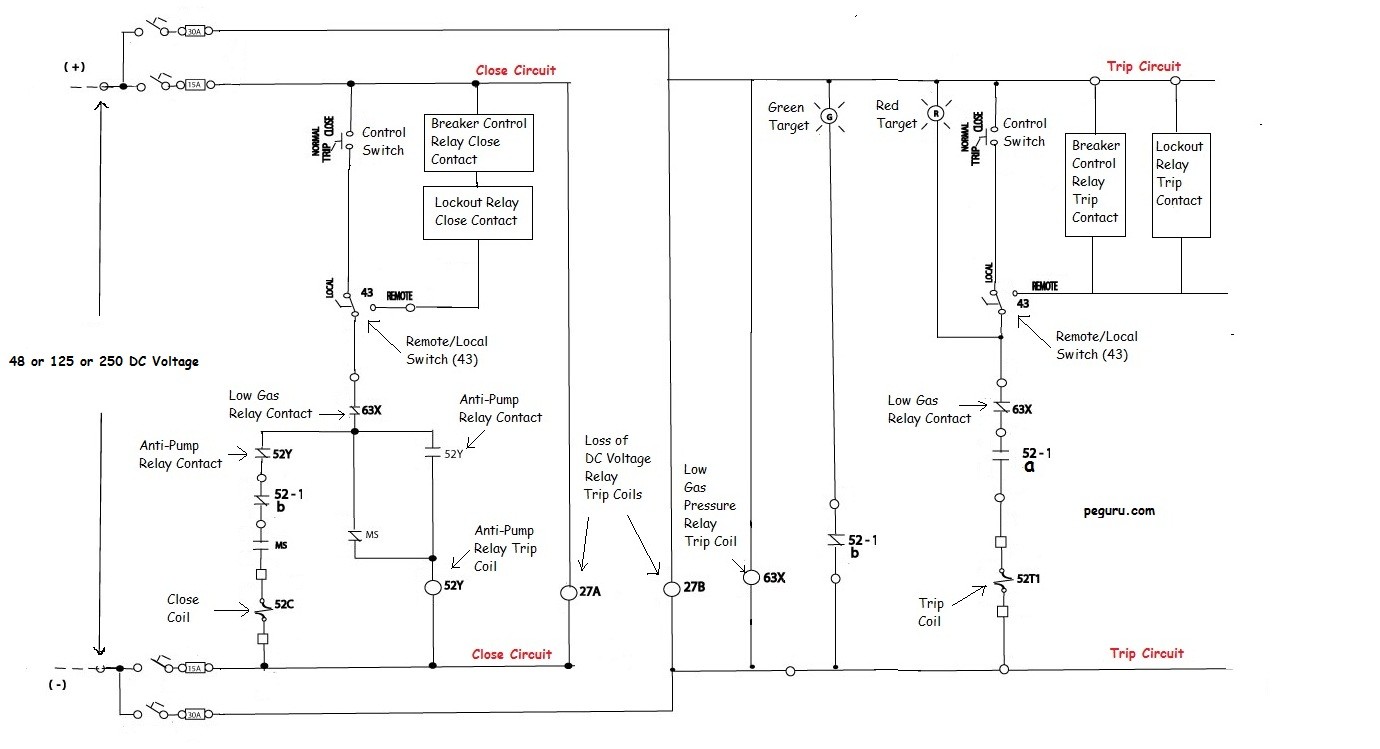
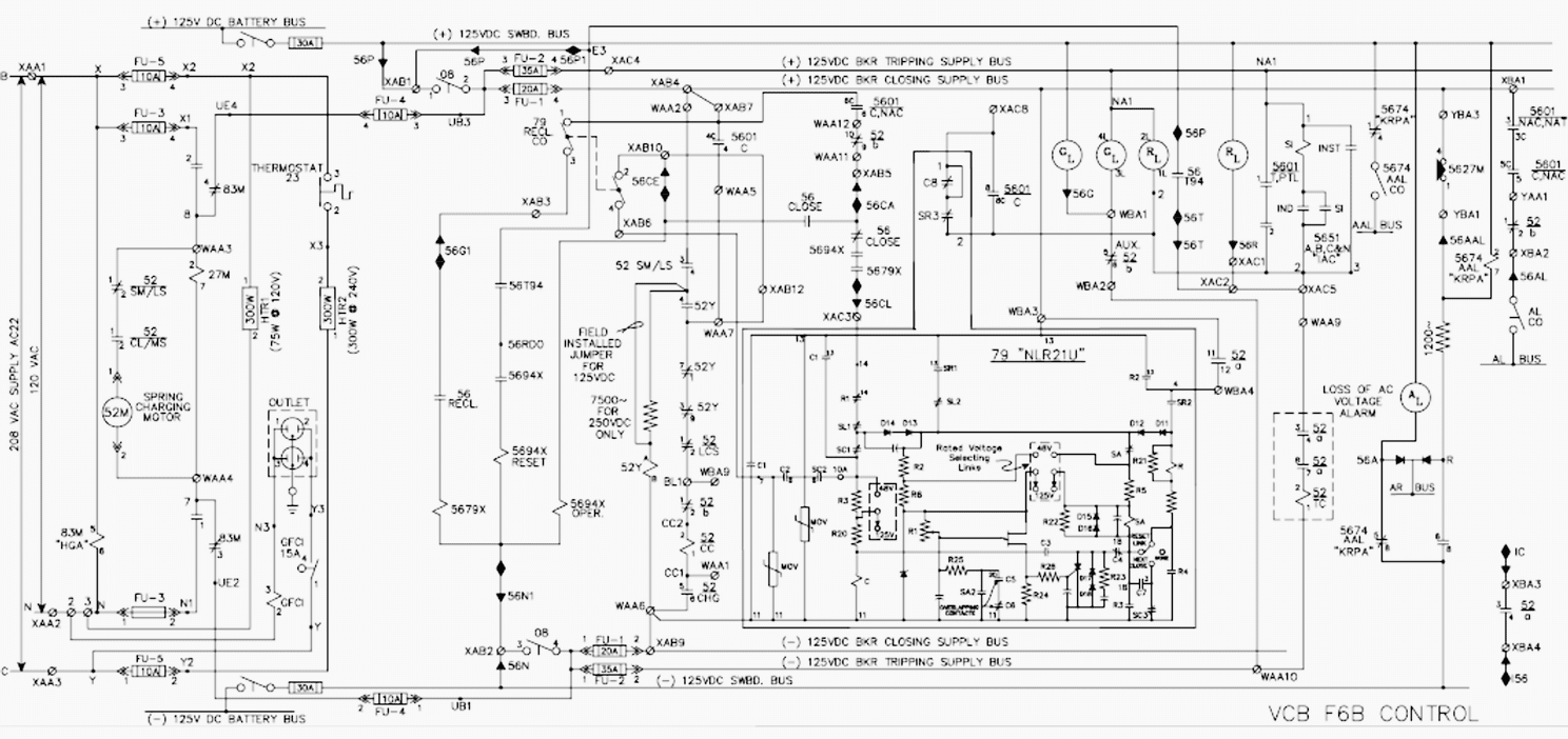
Vcb wiring diagram. Vcb panel wiring diagram pdf wiring diagram is a simplified all right pictorial representation of an electrical circuit. The working of vacuum circuit breakers is briefly explained below. As time goes on the size of the vacuum interrupter has reduced from its early 1960s size due to different technical developments in this field of engineering. If the backup camera is newly installed check whether the connection is correct or not. Even with limited rating say 60 to 100mva they are suitable for the majority of applications in rural areas. When the breaker operates the moving contact separates from the fixed contact and an arc is struck between the contacts.
It shows the components of the circuit as simplified shapes and the aptitude and signal connections with the devices. But still it is a developing technology. For individual component wiring please see the vcb x controller technical guide. The vcb x controller must be connected to 24 vac as shown in the wiring diagram below. Do you install the illustration above. The vacuum interrupter technology was first introduced in the year of 1960.
Reversing camera effect diagram of normal work display. Vcb x controller system wiring vcb x std wiring 1g p1 this is a complete typical orion vcb x control system wiring diagram. E bus digital room sensor. Vacuum circuit breakers are employed for outdoor applications ranging from 22kv to 66kv.
