Since this is an active circuit of uhf tv antenna booster it will require a 12v power supply to operate read more. It has a completely new low power architecture down to 27v with 65ma enabling battery powered small form factor handheld and embedded applications.

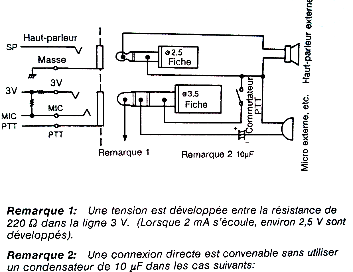
Microphone Dynamic Xlr Wiring Diagram Generalmotorspoerts
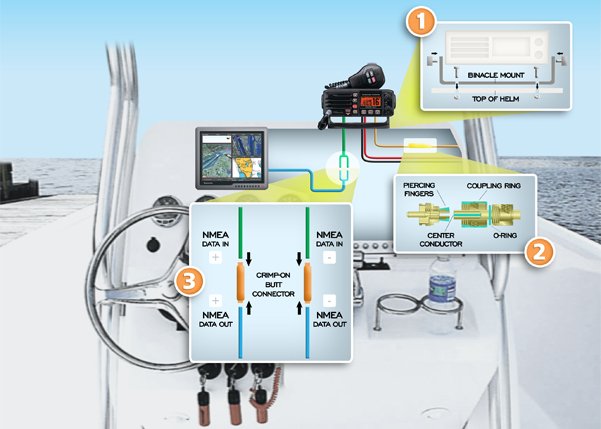
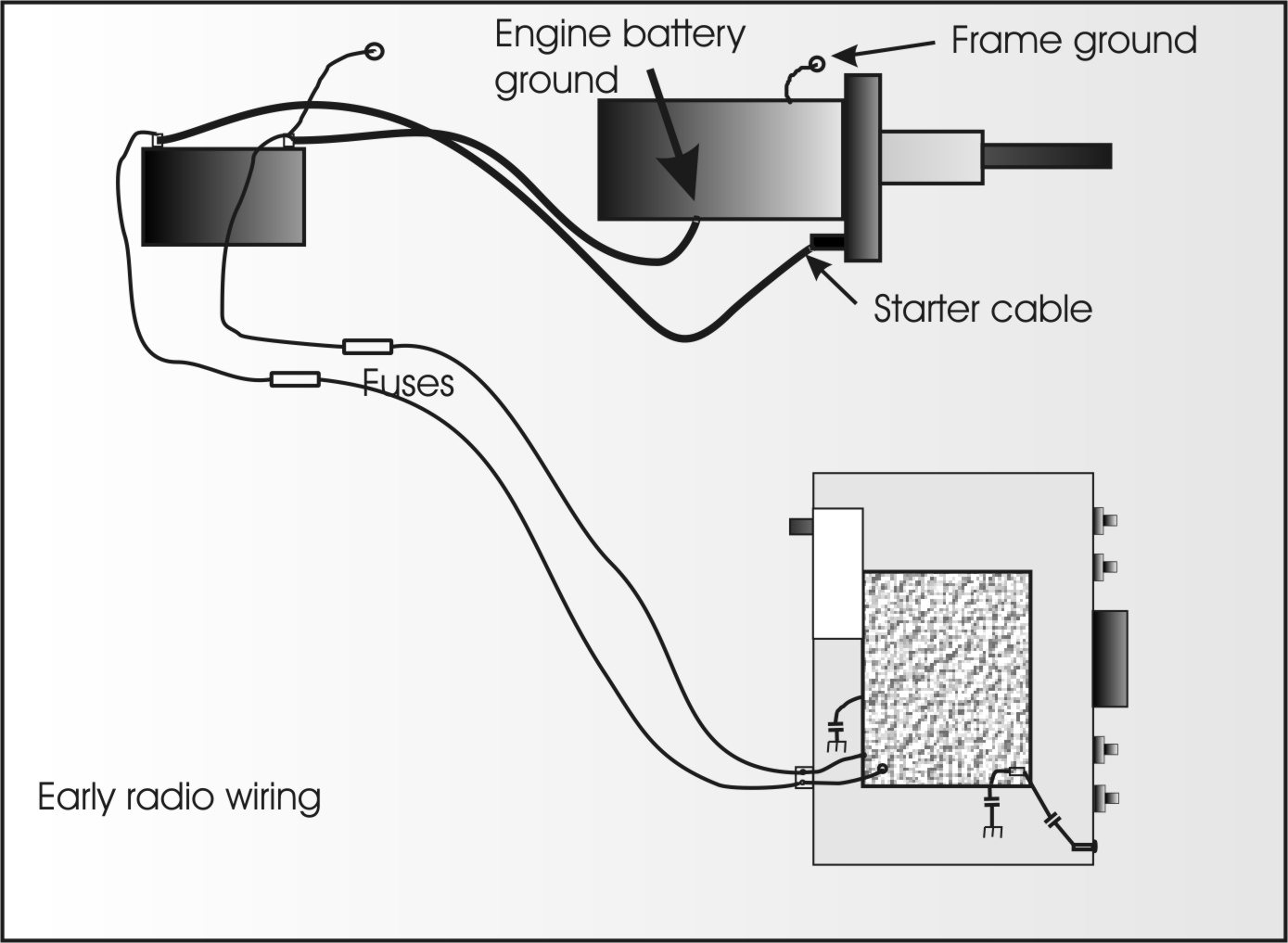
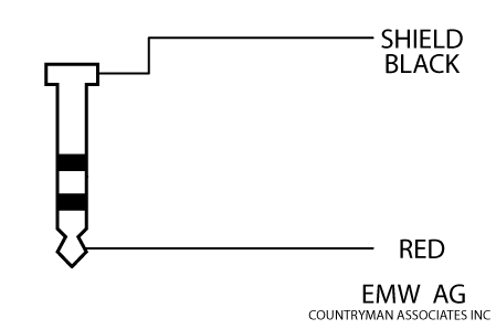
Uhf wiring diagram. The list below offers some microphone wiring information. Microphone wiring diagrams pop some mic wiring diagrams for ranger realistic alan cobra ge uniden yaesu kenwood icom radios. Our 25 foot cable works well for the ez hd antenna. This low cost antenna booster is simple and easy to buildit use single transistor bf180 to boost te uhf signal. This will determine whether you should be wiring the uhf unit up to battery power or an accessory output. Either way the ridge ryder uhf unit used in this review only has a few wires you need to worry about and they are handily colour coded for easy installation.
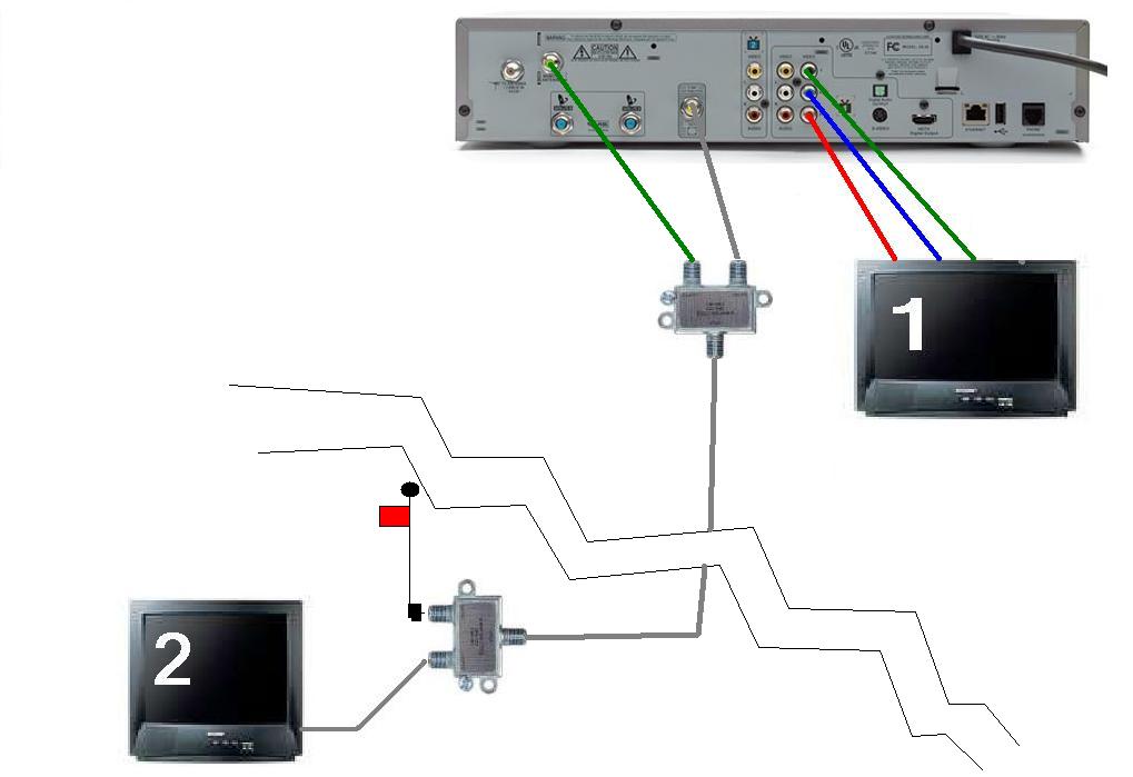
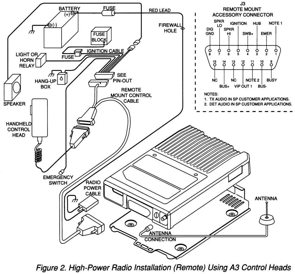
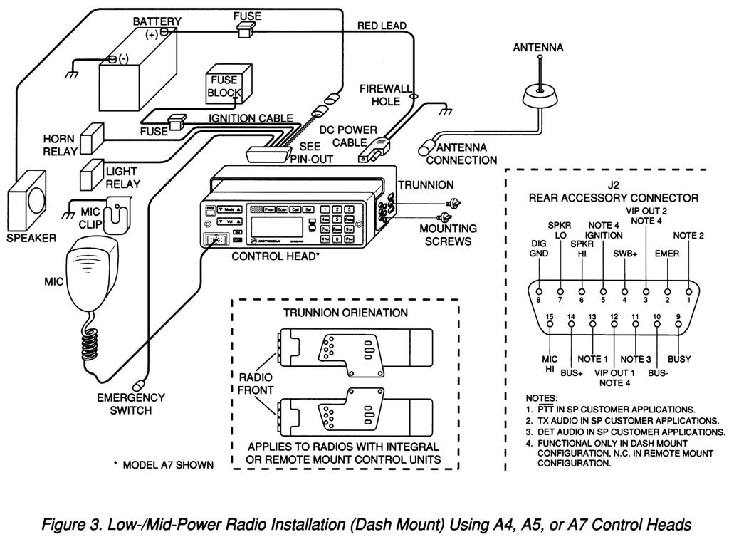
Some microphones may require extra jumpers or a slight variation on the diagrams shown. The title under the figure identifies the control head configurations. Use the diagram when planning the installation. The unit comes with mounting hardware and a fair length of wire giving you a. Uhf transmitter 5 pin input jack wiring the wiring diagrams included in this section represent the basic wiring necessary for the most common types of microphones and other audio inputs. From the ground block run coax cable indoors to the preamplifier power injector.
From the preamplifier output run coax cable to the ground block. A short coax cable is ran from the tv antenna output to the preamplifier input. Uhf fm transmitter description t1 transistor is mounted on the front of printed circuit board as indicated by the dotted line on the drawing board. May 09 uniden bearcat and 6 pin mike pinouts. Mic wiring can be frustrating enough but when you cant find the right wiring info it is just impossible. Diagrams for the microphone connections on many of the common cb radios as well as some popular amateur radio transceivers.
Also on the front face of the pcb should be placed either a short connection silver wire that connects positive supply bar and inductance l1 made directly on the pcb and parallel to it. Planning the installation 212 wiring diagrams figure 2 4 shows the wiring diagram the possible configurations. Radio mic wiring diagram. The chart and image above are correct for these models. We will continue to try to get all the information that we can listed on this page. The 4 foot cable is best for the hd stacker antenna.
The mini uhf connector tool motorola part number hln6695 is designed to securely. Antennas mounted indoors do not require a ground. Cable tv wiring doos and donts duration. This is the circuit diagram of uhf band tv antenna booster with 15db gain power. The as3993 uhf reader chip is the first in the next generation of epc class 1 gen2 rfid reader ics from austriamicrosystems. Hdtv outdoor amplified antenna fp 9000 360 uhfvhffm 150 miles review duration.
