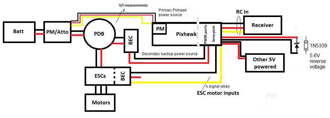
See wiring diagrams on page 8 for contact positions and wire colors for the ubec 1s. Select from the options below to show the appropriate wiring diagram depending on your particular setup.

What Are Esc Ubec And Bec Oscar Liang
Ubec wiring diagram. I am installing a 3 amp ubec with a 30 amp esc that has a built in bec in order to handle 6 micro servos the esc says that the built in bec will handle up to 4. Please help any comment would be great. System wiring below is a diagram to show how to wire a typical brushless motor system. Also note the clipped red wire on the speed controls receiver lead a must to prevent damage to your electronics. Ubec wiring diagram the ubec is an external switching mode dc dc regulator. Probably this question has been posted before but i could not find it.
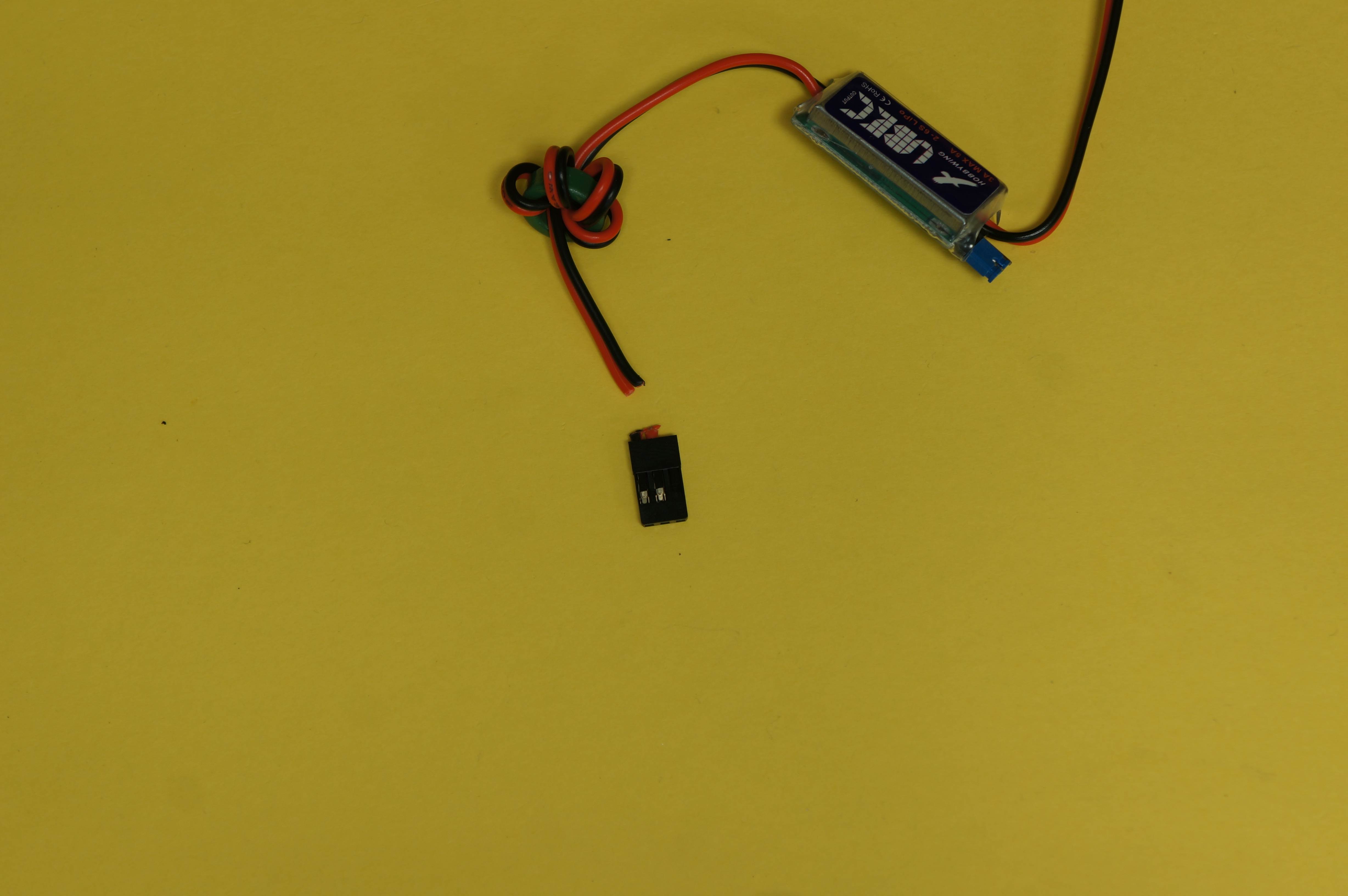
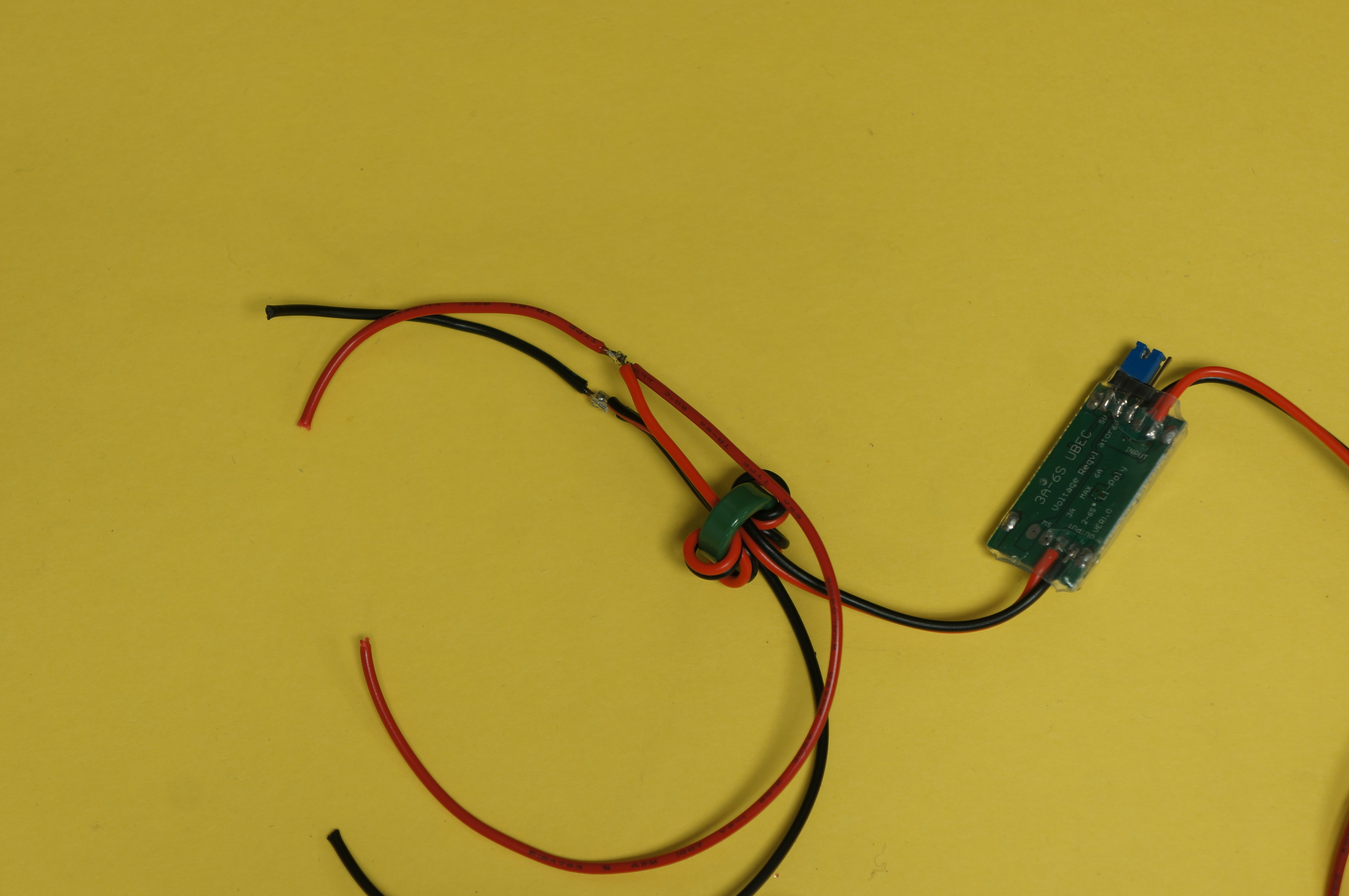
To the diagram below then connect the input end of the ubec to the battery wires. Rather then cut the wire carefully remove the wire and pin from the plug and tape it back out of the way so that you can re insert it at a later day. Note the soldered connection between the external bec and the escs battery lead right after the battery connector this is the easiest place to tap into the power leads. Question proper wiring for a ubec power systems. Connect power and ground to the controller. Internal esc bec external ubec receiver pack battery pack wiring 1 battery pack 2 series battery packs 3 series battery packs 2.
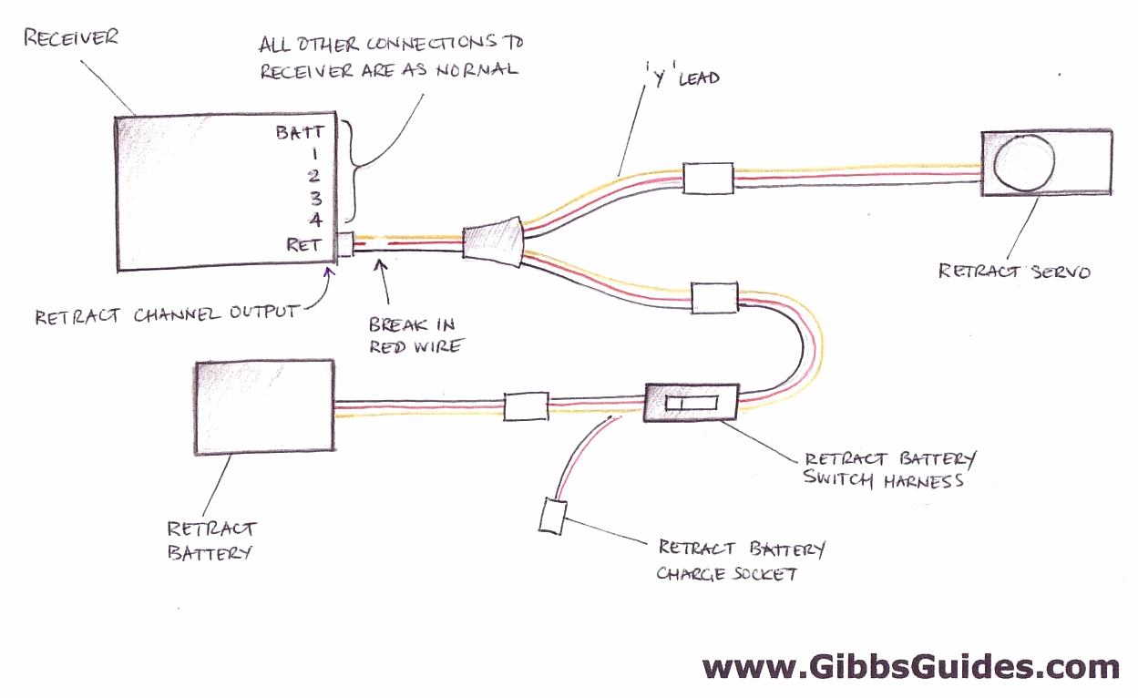
Confused with how to add ubec for esc that doesnt have built in bec. Wiring ubec 1c controllers for a single ubec 1c controlling one valve. How to wire up a ubec with an esc that has a built in bec connectors motor receiver please note that the redorange ve wire from the esc electronic speed controller to the receiver is broken. Use 1 amp fuse for 12v 05 amp for 24v on positive controller leads. A traditional bec setup.


