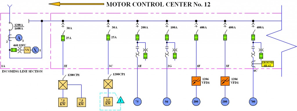
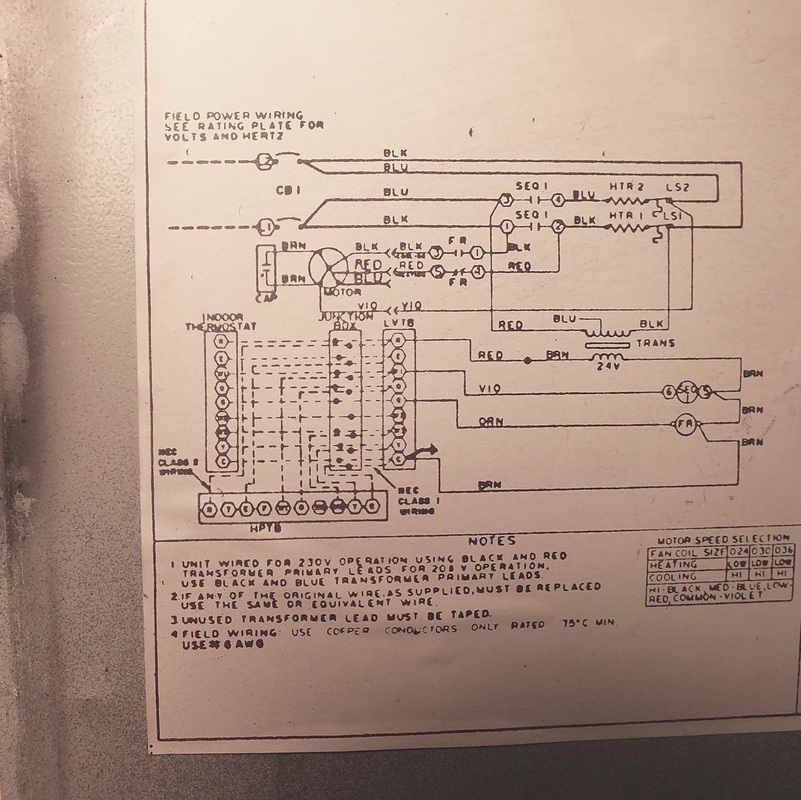
Basics 16 wiring or connection diagram. Electrical symbols and electronic circuit symbols are used for drawing schematic diagram.

17 Best Electrical Symbols Images Electrical Symbols
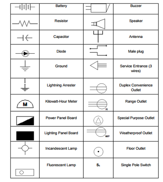
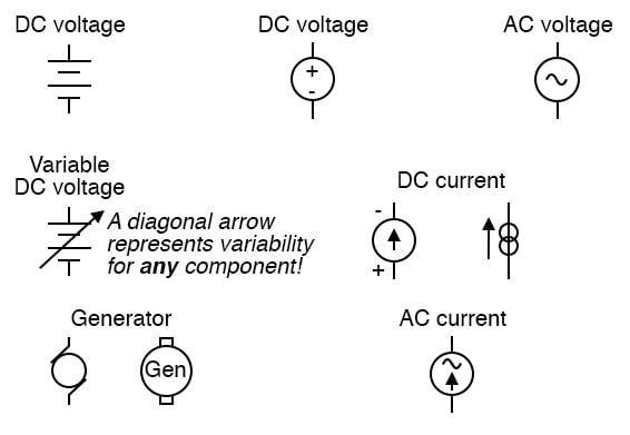
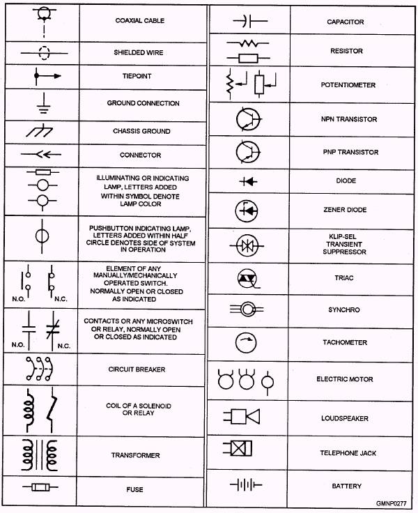
Standard symbols used for electrical wiring diagram. It wasnt so easy to create electrical symbols and electrical diagram as it is now with electrical diagram symbols offered by the libraries of electrical engineering solution from the industrial engineering area at the conceptdraw solution park. The schematic symbols for most major circuit diagrams can be found in this following images. Electrical symbols are used to represent electrical and electronic devices in schematic diagrams. Line diagrams provide a fast easy understanding of the connections and. Symbol for control and wiring diagrams company document ns 503 cad name description symbol 07 02 02 make contact switch 07 13 02 contactor contact open in the deenergized position 07 13 05 circuit breaker 07 13 06 disconnector isolator off load 07 13 08 switch disconnector on load 07 21 08 fuse disconnector. This article shows many of the frequently used electrical symbols for drawing electrical diagrams.
Though these standard symbols are simplifiedthe function descriptions can make you understand clearly. Typical electrical drawing symbols and conventions. Here is a standard wiring symbol legend showing a detailed documentation of common symbols that are used in wiring diagrams home wiring plans and electrical wiring blueprints. Electrical symbols virtually represent the components of electrical and electronic circuits. Cross reference mz081001en effective november 2013. Ansiieee standard device numbers 1 master element 2 time delay starting or closing relay 3 checking or interlocking relay 4 master contactor.
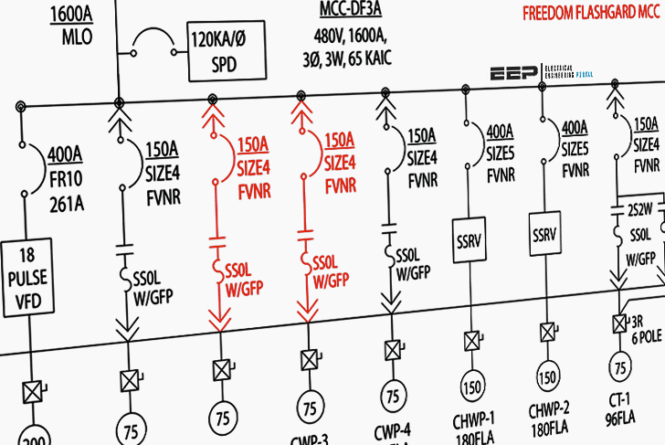
The symbols represent electrical and electronic components. This solution provides 26 libraries which contain 926. All you need is a powerful software. There are different country specific standards iec british ansi and as australian standard that define the symbols used in circuit diagrams across the world. Line diagrams a line ladder diagram is a diagram that shows the logic of an electrical circuit or system using standard symbols. Wiring diagrams use simplified symbols to represent switches lights outlets etc.
The following tables describe the device and show the symbol by area of usage. Electrical symbols electronic symbols. Basics 15 wiring or connection diagram. Used in any one facility. The purpose of this document is to provide a simple cross reference of common schematicwiring diagram symbols used throughout various parts of the world. How to create electrical diagram.
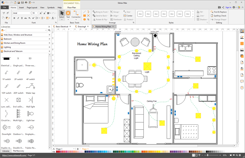
Edraw max an electrical diagramming program was the first software to demonstrate standard electrical symbols on computer screens. A line diagram is used to show the relationship between circuits and their components but not the actual location of the components.
