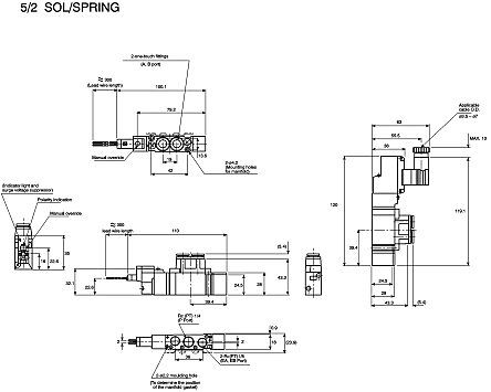
It shows the parts of the circuit as simplified forms and the power and also signal connections between the devices. Smc valve bank wire diagram.

Download Cat 5 Wiring Diagram Camera Security
Smc valve bank wiring diagram. It reveals the parts of the circuit as streamlined forms and the power and also signal links between the gadgets. Typical cordset color code m12 female 4 pin a code standard key. By headcontrolsystem collection of smc solenoid valve wiring diagram. 2 port solenoid valve. Pressure control equipment fittings and tubing flow control equipment switches sensors. Electronic regulator wiring wiring caution.
B is used for the internal wiring of each station regardless of valve and option types. March 31 2019 by larry a. A wiring diagram is a simplified standard pictorial depiction of an electric circuit. Connect the cable to the connector on the body with the wiring arranged as show below. Station wiring wiring side 1 for single wiring sq1000 017 to 023nm sq2000 025 to 035nm sq12000 tfj38gb 20 26 1 2 3 double wiring connected to sol. Directional control valves air cylinders rotary actuators air grippers electric actuators vacuum equipment.
Brown 24 node and inputs white 24 valves blue 0 node and inputs black 0 valves system wiring. A wiring diagram is a simplified conventional photographic representation of an electric circuit. Smc solenoid valve wiring diagram gallery smc type high quality fittings aq340f 04 00 o d 4mm quick exhaust. Process valves temperature control equipment static neutralization equipment silencers. Further use dc power with sufficient capacity and a low rip. Smc type high quality fittings aq340f 04 00 o d 4mm quick exhaust.
Proceed carefully as incorrect wiring can cause damage. Mixed single and double wiring is available as. Wiring wiring on the double single low no. Wellborn assortment of smc solenoid valve wiring diagram. Power wiring for smc ex260 sen ex260 sen power wiring in not the same as the ex50 0 gen1 or ex250 sen1. Air preparation equipment modular frl.


