Collection of three wire alternator wiring diagram. This rotor spins past wire coils causing a magnetic field.
26cb6d4 1971 Ford F 250 Alternator Wiring Diagram Wiring
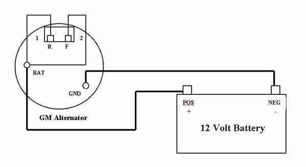
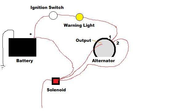
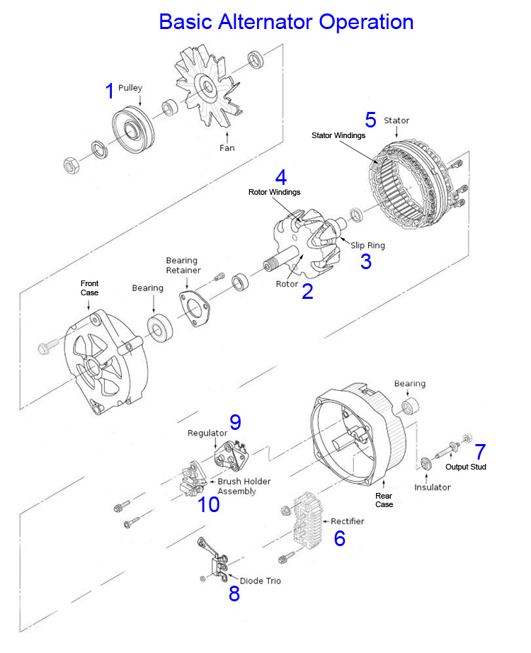
Simple alternator wiring diagram. Ford alternator wiring diagram this is the diagram of every components in the alternator. How alternator works diy voltage regulator. The second part involves the control circuits. Three wire alternator wiring diagram 3 wire alternator wiring diagram chevy best fancy e wire alternator diagram model simple wiring diagram. This is the most basic way to connect an alternator to make a charging set or to run an inverter from a stationary engine. Connect the opposite end of this wire to the starter solenoid.
Starters are turned on and off and alternator output is. Wiring a 3 wire alternator with an idiot light great lakes 4x4. It shows the parts of the circuit as streamlined forms and also the power as well as signal links in between the gadgets. A wiring diagram is a simplified conventional photographic depiction of an electric circuit. Vw parts electrical wiring electrical diagram electrical installation electrical engineering engine repair mr2 small engine mechanical engineering. Figure 1 below is a block diagram or a functional diagram of an alternator and its connections to the remainder of the automobile electrical system.
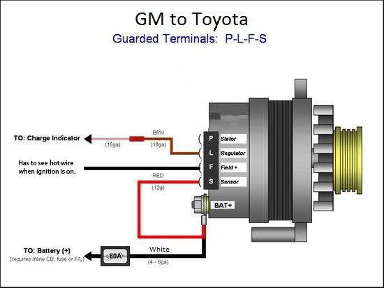
Disconnect the battery negative terminal. Collection of delco 3 wire alternator wiring diagram. Simple alternator wiring diagram. May 16 2019 by larry a. It is a diagram for the alternator in a ford focus see also ford focus repair manual ford escort ford f 100 ford taurus ford mustang ford model t ford gt40 ford thunderbird ford shelby cobra and other ford cars that use the similar alternator. The other terminal is the exciter.
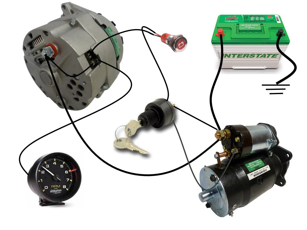
The process for wiring a starter and an alternator on a car is divided into two parts. A wiring diagram is a simplified traditional pictorial depiction of an electric circuit. The largest offroad forum in the midwest. Wiring this alternator is well within the capabilities of anyone with average mechanical skills. The first part deals with the power circuit connections because starters consume and alternators produce great amounts of power. Connect a length of 10 gauge wire to the output stud on the back of the alternator using a solderless ring connector.
It reveals the elements of the circuit as streamlined shapes and the power and signal links in between the gadgets. I run the fiesta alternator from the flywheel of a 1942 lister dk and the.
Gallery of Simple Alternator Wiring Diagram