Tech support and customer service. In north america call 1 800 272 8559 for 24 hour.

Scully Sensors
Scully system wiring diagram. Scully spill prevention and grounding systems have to the scully socket truck monitor and ground bolt all system components including sensors wiring. Enclosure earth ground connection. Scully will remain a steadfast resource for you as we weather this crisis together. As an integrated company with in house manufacturing and technical support we can respond immediately. More posted in. Shortening the sensor shaft the sensor shaft may be shortened to a minimum of 512 140mm when measured.
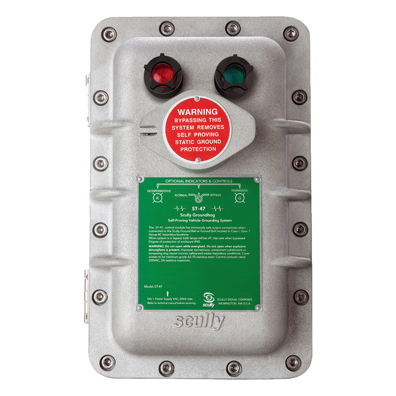
The sp to sensor should be wired in accordance with the appropriate scully wiring diagram. To ensure that it will always detect an overfill condition the controller uses pulsed signals which continuously check the entire system operation including the controller wiring connections and sensors. Dwg 61121 field wiring diagram st 47 115240 elk st 47 groundhog technical manual diagram appendix 612 dwg 61121 field wiring diagram st 47 115240 elk page 28. Please contact us if we can help in any way. We wish everyone stays safe and remains well. We want to assure you that scully is here to produce the equipment and provide the services you depend on.
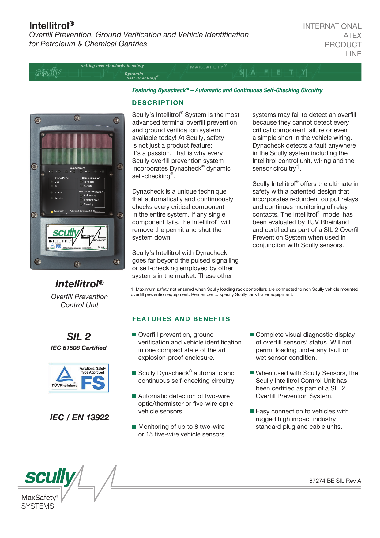
Scully recommends the use of our special cable for wiring on a vehicle. Scully systems nv 32015560070 sales at scullybe. If using conduit 22 awg 033 mm² or larger wires should be employed. Self proving vehicle grounding veri cation system diagram appendix 611 dwg 61332 internal wiring diagram st 47 elkd page 27. The system incorporates scullys unique and exclusive dynacheck concept. Wiring diagram typical loading rack control dwg sensor stc overfill prevention system detects the overfill condition and signals for shutdown of loading.
If the sensor comes in contact with. Scully signal is fully operational during the covid.


