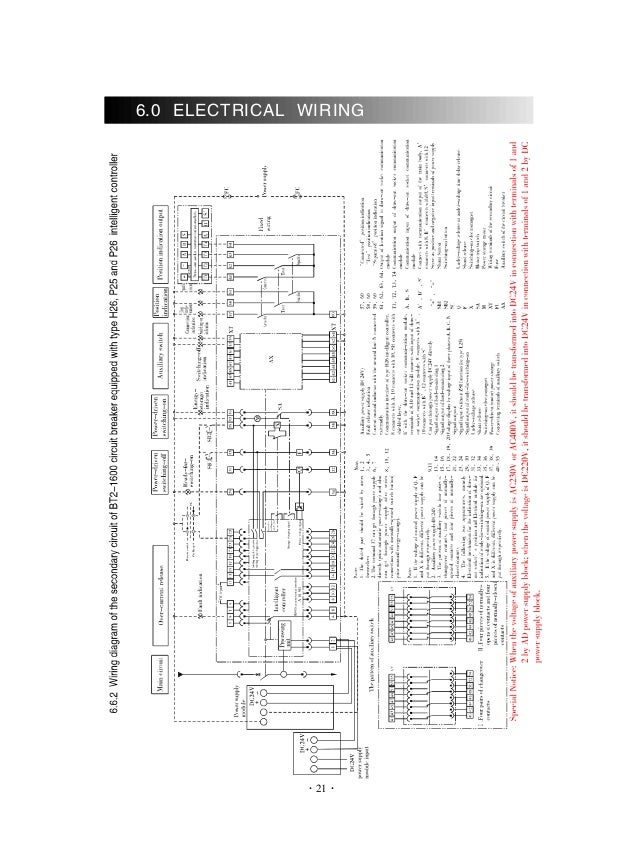
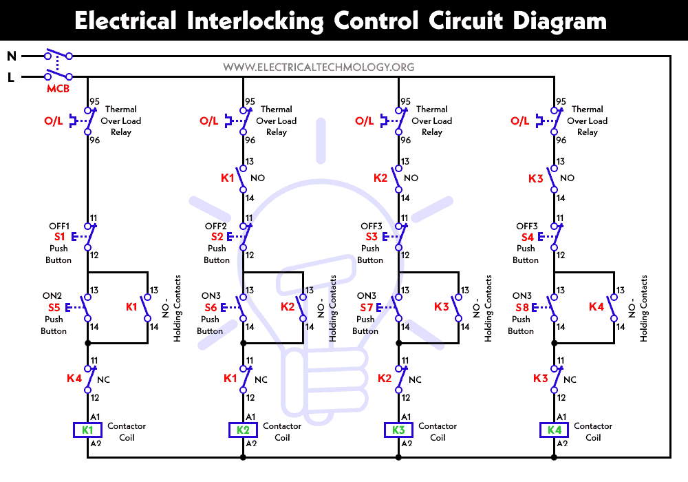
Refer to the wiring diagram page 54 for dip switch settings each control contact must be suitable for a 5 v dc low energy circuit. And magneto thermal release is.
Download 91 Geo Tracker Wiring Diagram
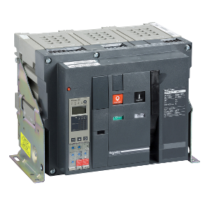
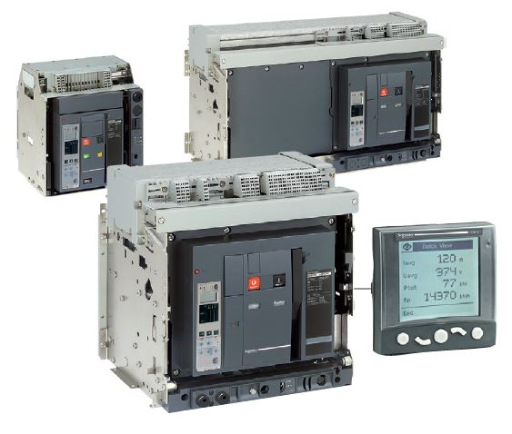
Schneider acb wiring diagram. This book contains examples of control circuits motor starting switches and wiring diagrams for ac manual starters drum switches starters contactors relays limit switches and lighting contactors. Find insight on schneider electrics masterpact mtz air circuit breakers acb compact nsx nsxm molded case circuit breakers mccb acti 9 miniature circuit breakers mcb canalis busbar trunking to the tesys motor starters and more. Bpfe xf when connected to a remote control panel the xf closing release 085 to 11 un can be used to close. Masterpact nw drawout circuit breakers low voltage power circuit breaker insulated case circuit breaker iec rated. Programmable engine exerciser connection if provided refer to page 53 load disconnect feature connections see wiring diagram refer to page 54 for dip switch settings figure 1 2. By adding an xf closing release the circuit breaker can be closed remotely.
Tripping coil under voltage coil why used in acb with their function details. Schneider electric products and equipment should be installed. 0140ct9201 pdf 21 mb 21 mb. 1 masterpact nt. Masterpact circuit breakers are available in square d or schneider electric brands. Schneider electric does not grant any right or license for commercial use of the guide or its content except for a non exclusive and personal license to consult it on an as is basis.
Nec and other local wiring codes. Schneider mccb wiring diagram crossflagsmini co uk 1 pole 6ka 05a 1a 16a 23a 4a 6a 10a 13a 16a. Internal wiring diagram of new dn release ct r phase ct y phase ct b phase t1 m1 t2 m2 t1 m1 t2 m2 t2 m1 t2 m2 s o l bime xxx sc magnetic c xxx shorting link for fixing ef. Industrial electrical 31625 views. Wiring diagram acb schneider a delta delta is a 3 phase connection without a neutral youre going the same voltage on the primary to the same voltage of the secondary but its used for high current applications like stated in this article. Acb is not tripping in case of overload or short circuit fault probable cause a connection between ct.
Press the electrical closing pushbutton. Markings for push in type terminals. Electrical diagrams 28 discovering masterpacts accessories 30 micrologic control units 30 indication contacts 31 auxiliaries for remote operation 33 device mechanical accessories 36 chassis accessories 38 inspecting and testing before use 40 initial tests 40 what to do when the circuit breaker trips 41 maintaining masterpact performance 42. This function can be disabled by wiring the closing release in series with the pf ready to close contact. Wiring diagrams for masterpact nt circuit breakers. The guide includes coordination for electrical distribution for motor circuits use of lv switches and.
