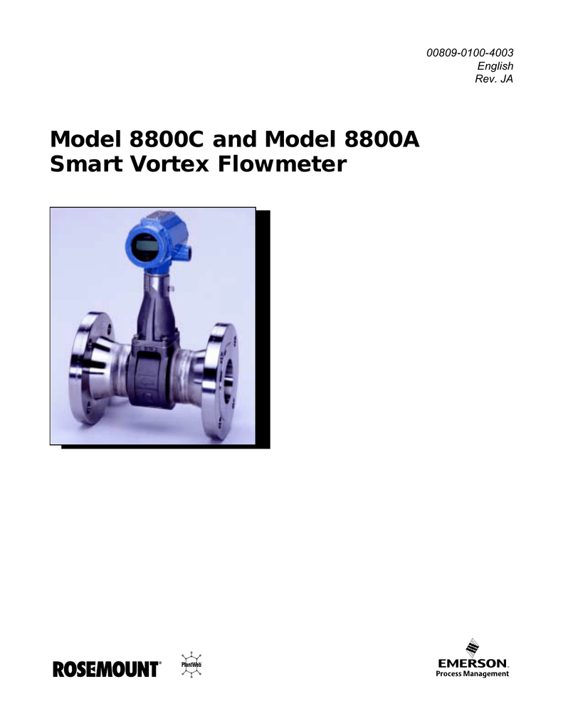
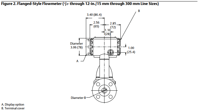
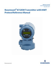
Power supply with counter rosemount 8800d series vortex flowmeter. The rosemount 8800d vortex flowmeter with foundation fieldbus consists of a meter body and transmitter.
Rosemount 8800d Series Vortex Flowmeter Emerson Process
Rosemount 8800d wiring diagram. The rosemount 8800d vortex flowmeter consists of a meter body and transmitter and measures volumetric flow rate by detecting the vortices created by a fluid passing by the shedder bar. A sensor is located at the end of the. The meter body is installed in line with process piping. 420 ma and pulse wiring with electronic totalizercounter 250 ω 100 ω r 100 kω a. A sensor is located at the end of the. The bracket to facilitate field wiring and conduit routing.
The meter body is installed in line with process piping. Quick start guide april 2018. The starred options should be selected for best delivery. Model product description rosemount. Non clog design unique all welded gasket free construction which has no ports or crevices that can clog. Housing can be repositioned on the bracket to facilitate field wiring and conduit routing.
10 rosemount 8800d series vortex flowmeter. 22 install remote electronics if you order one of the remote electronics options options r10 r20 r30 or. Non clog designunique all welded gasket free construction which has no ports or crevices that can clog. The rosemount 8800d delivers reliability safety and maximum process availability rosemount reliabilitythe rosemount 8800d vortex eliminates impulse lines ports and gaskets to improve reliability. Page 18 quick start guide october 2018 figure 5 4. Rosemount 8800d vortex flowmeter ordering information the standard offering represents the most common options.
Rosemount 8800d ambientprocess temperature limits the following orientations are recommended for applications with high process. It measures volumetric flow rate by detecting the vortices created by a fluid passing by the shedder bar. Important do not over tighten hex screw. The expanded offering is subject to additional delivery lead time. Cable connections refer to figure 8 and the instructions on page 7 to connect the loose end of the coaxial.
