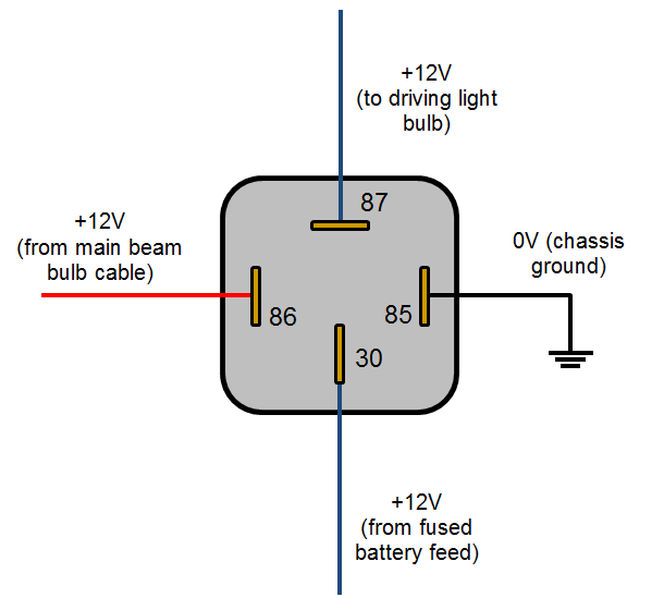
A wiring diagram is a straightforward visual representation with the physical connections and physical layout of your electrical system or circuit. The relay contacts are isolated from the input power and the dry contact input.

Norlake Zer Wiring Diagram Diagram Base Website Wiring
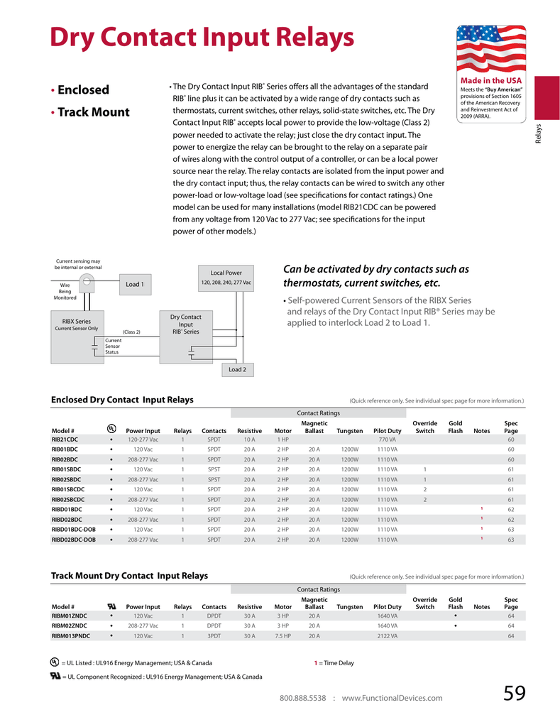
Rib01bdc wiring diagram. The power to energize the rib series comes from the load being controlled or a local power source near the relay. How to wire a 4 or 5 pin relay duration. 42 ma at 120 vac notes. Class 2 horse power. Rib01bdc enclosed relay 20 amp spdt class 2 dry contact input 120 vac power input power input. There is a lot of extra wiring in this enclosure which not only takes up space but also increases the diculty and time associated with installation.
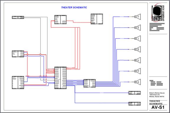
It shows the elements of the circuit as streamlined forms as well as the power and also signal links between the devices. Variety of ribu1c wiring diagram. 20 a power supply. If more than one dry contact rib shares a single dry contact input whiteblue must be common. Blk wht control neutral circuit dry contact input whtred whtblu org comm nic. Sub panel to remainder of panel switch breaker indicator light enclosure conduit sub panel to remainder of panel fuse switch h n g h n g enclosed 4 amp pspt2rb4 pspw2rb4 condense work space.
Dry contact input relay specifications. Dry contact input operation. 1200 w pilot duty rating. Functional devices 2175 each add to cart. How why you should use them on your project tech tip tuesday duration. Wire ribx series current sensor only low voltage class ii dry contact input rib series local power 120 240 277 vac current sensing may be internal or external load 1 dry contact input relays rib21cdc rib01bdc rib01sbdc rib02bdc rib02sbdc ribm01zndc ribm02zndc ribm013pndc current sensors ribxkf ribxktf ribxka ribxkta ribxga ribxgf ribxgta.
A wiring diagram is a streamlined standard photographic depiction of an electric circuit. Wed jul 8. Rocky x tv 396749 views. The dry contact input rib series is controlled by class 2 circuits with a dry contact from a bas controller thermostat switch another relay or a solid state switch. It shows how the electrical wires are interconnected and can also show where fixtures and components might be attached to the system. Ribu1c wiring diagram what is a wiring diagram.
Close whitered wire to whiteblue wire to activate relay.


